
Y-Gantry Wheels
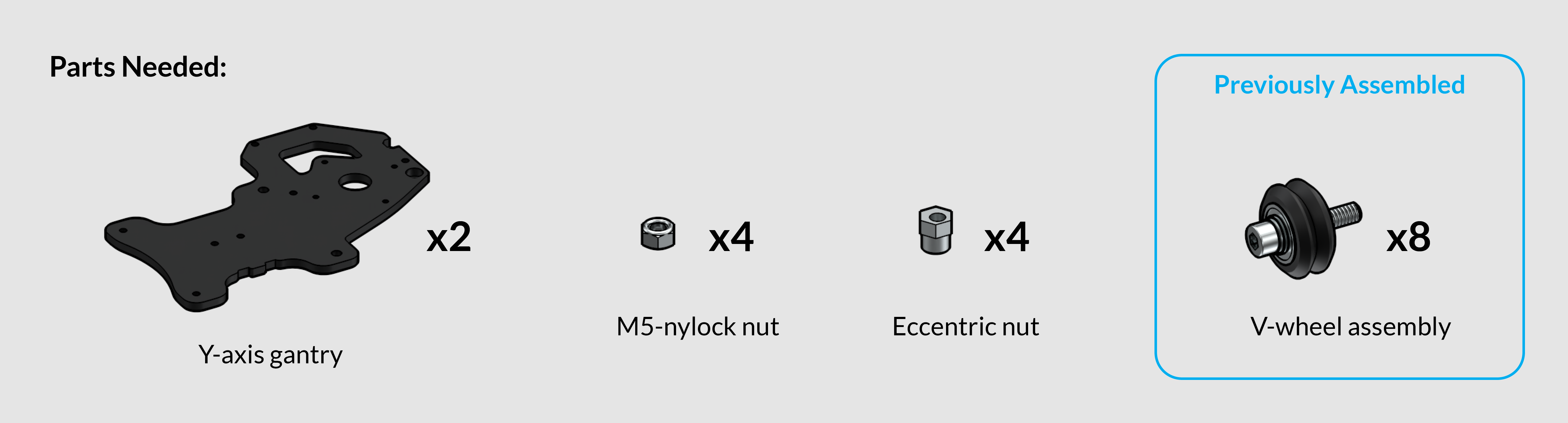

Install two v-wheel assemblies to each Y-axis gantry using nylock nuts. Similar to previous steps, use the M5 Allen key and included wrench to firmly secure the nylock nuts.
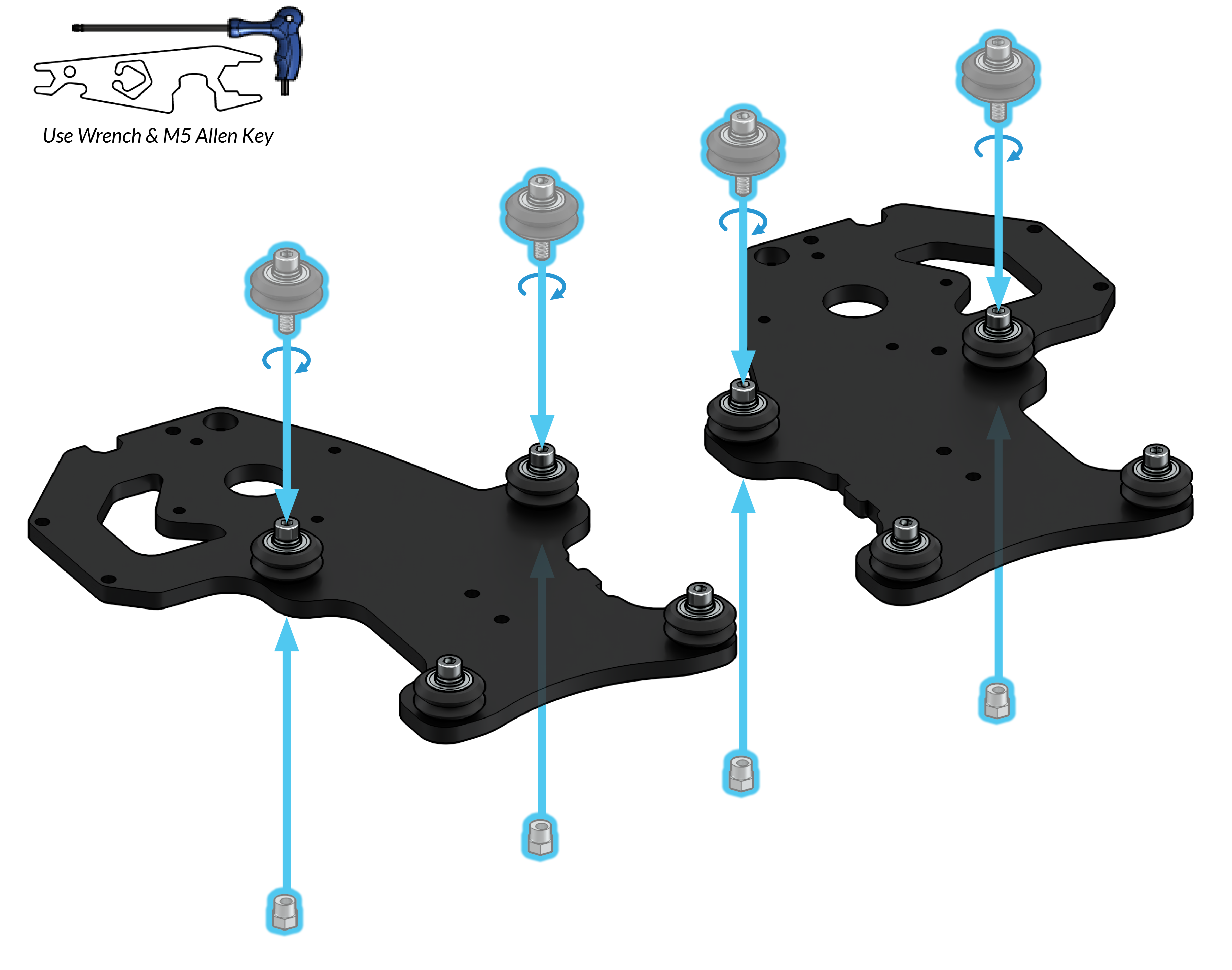
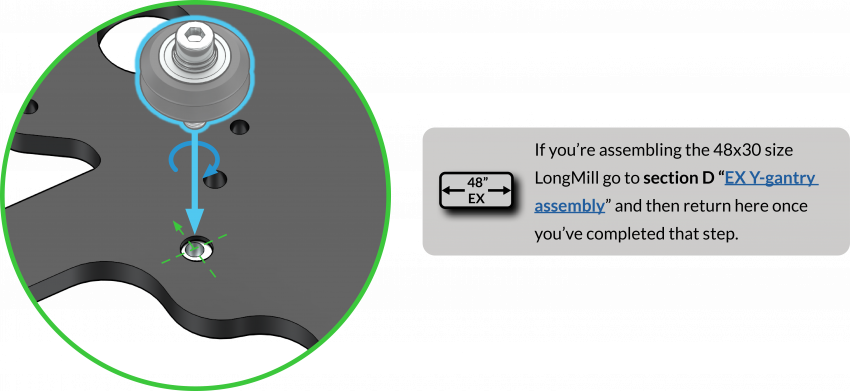
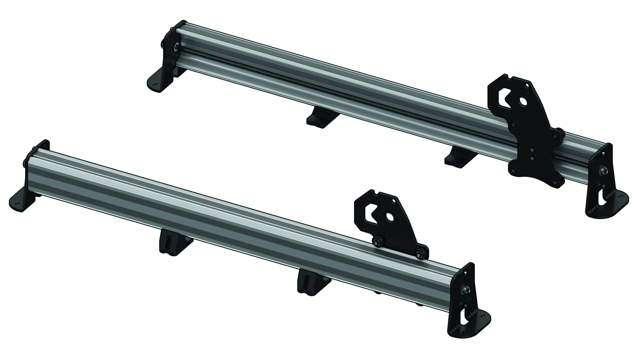
Now, loosely install two v-wheel assemblies in the upper set of holes on each Y-axis gantry, using eccentric nuts. Orient the inner holes of the eccentric nuts away from the bottom edge of the gantry (pictured below). ![]()
Y-axis Anti-backlash Nuts

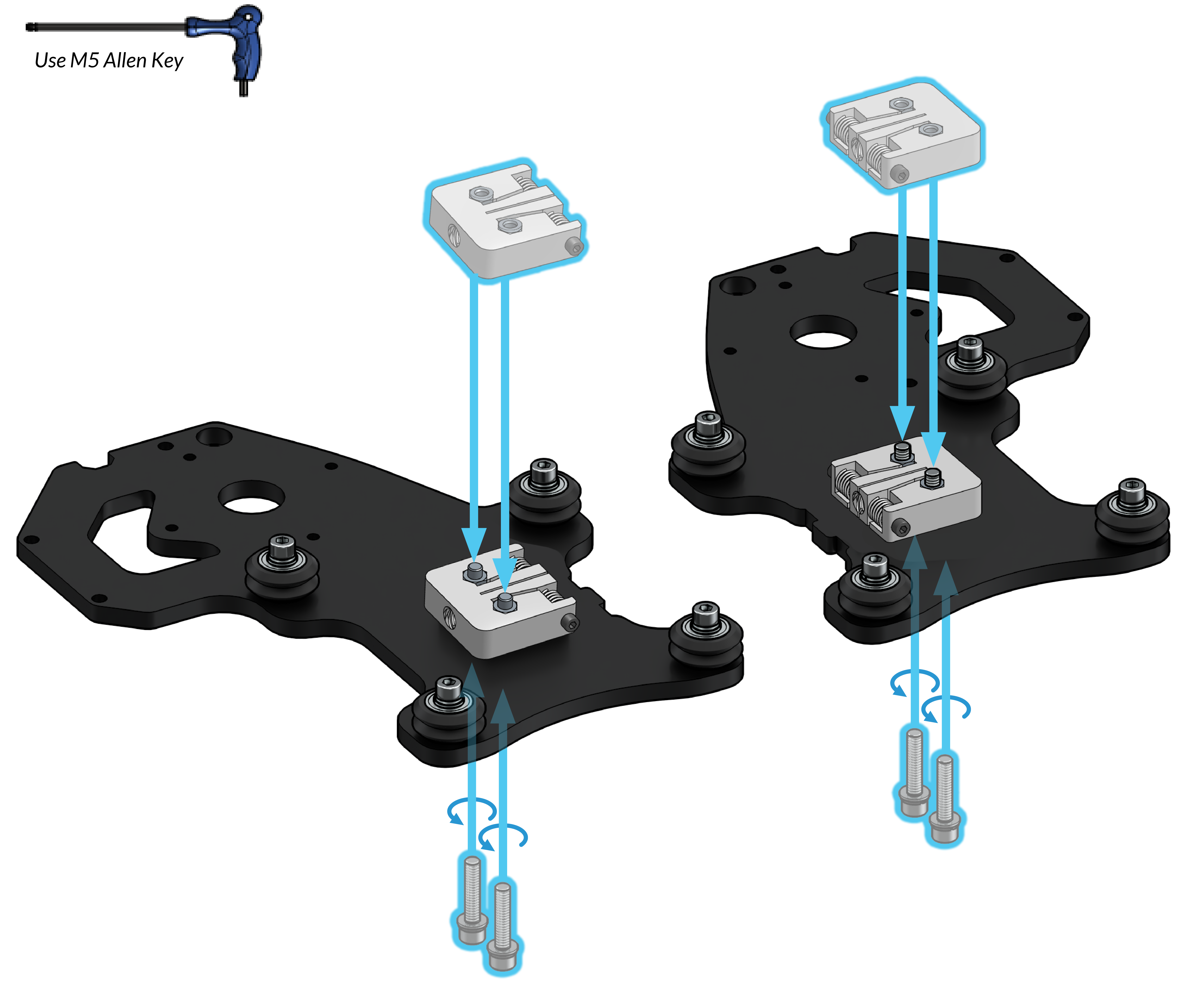
Using two M5-25mm bolts, loosely attach the two Delrin anti-backlash nuts to the back of each Y-gantry
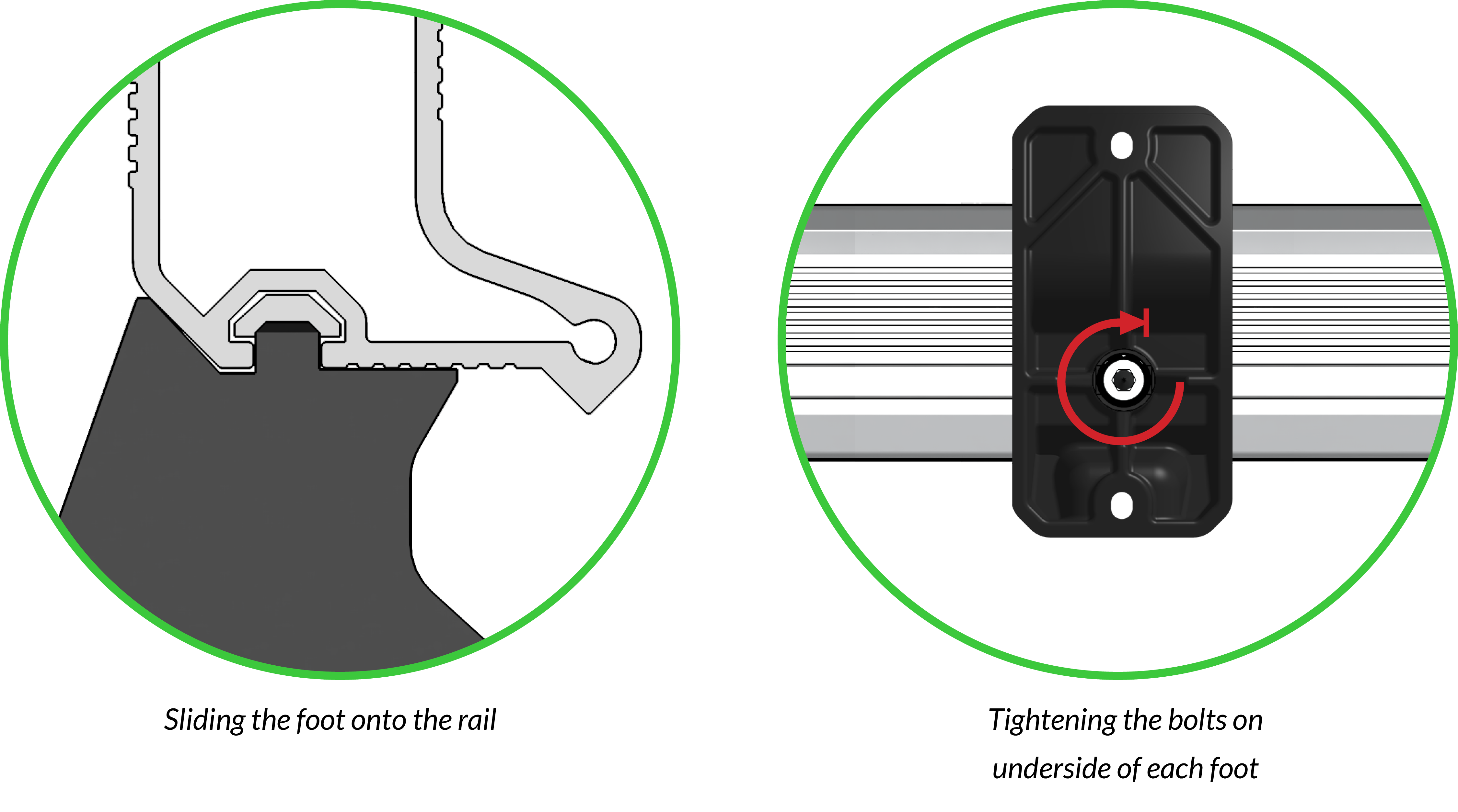
Y-axis Middle Feet
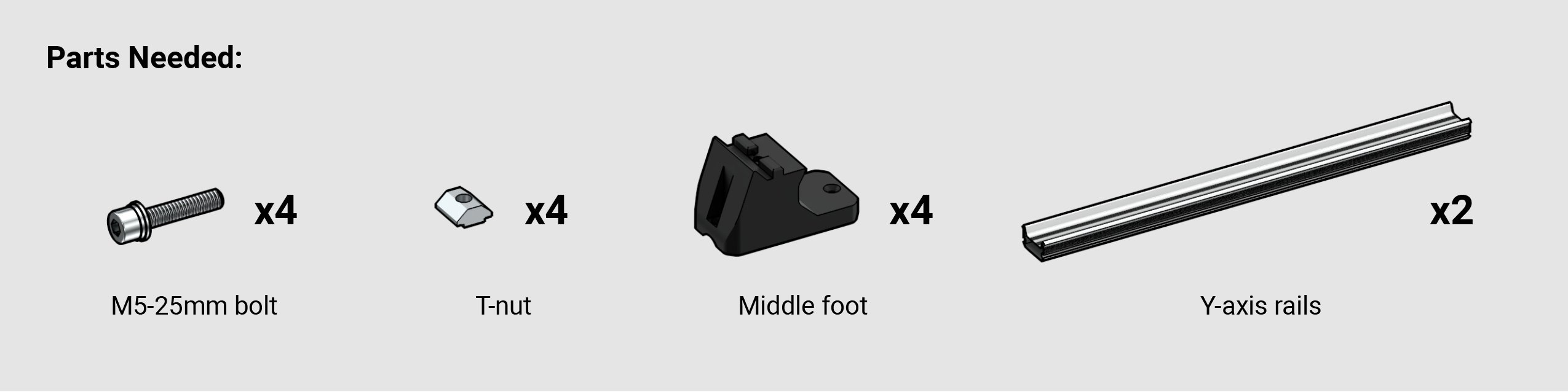
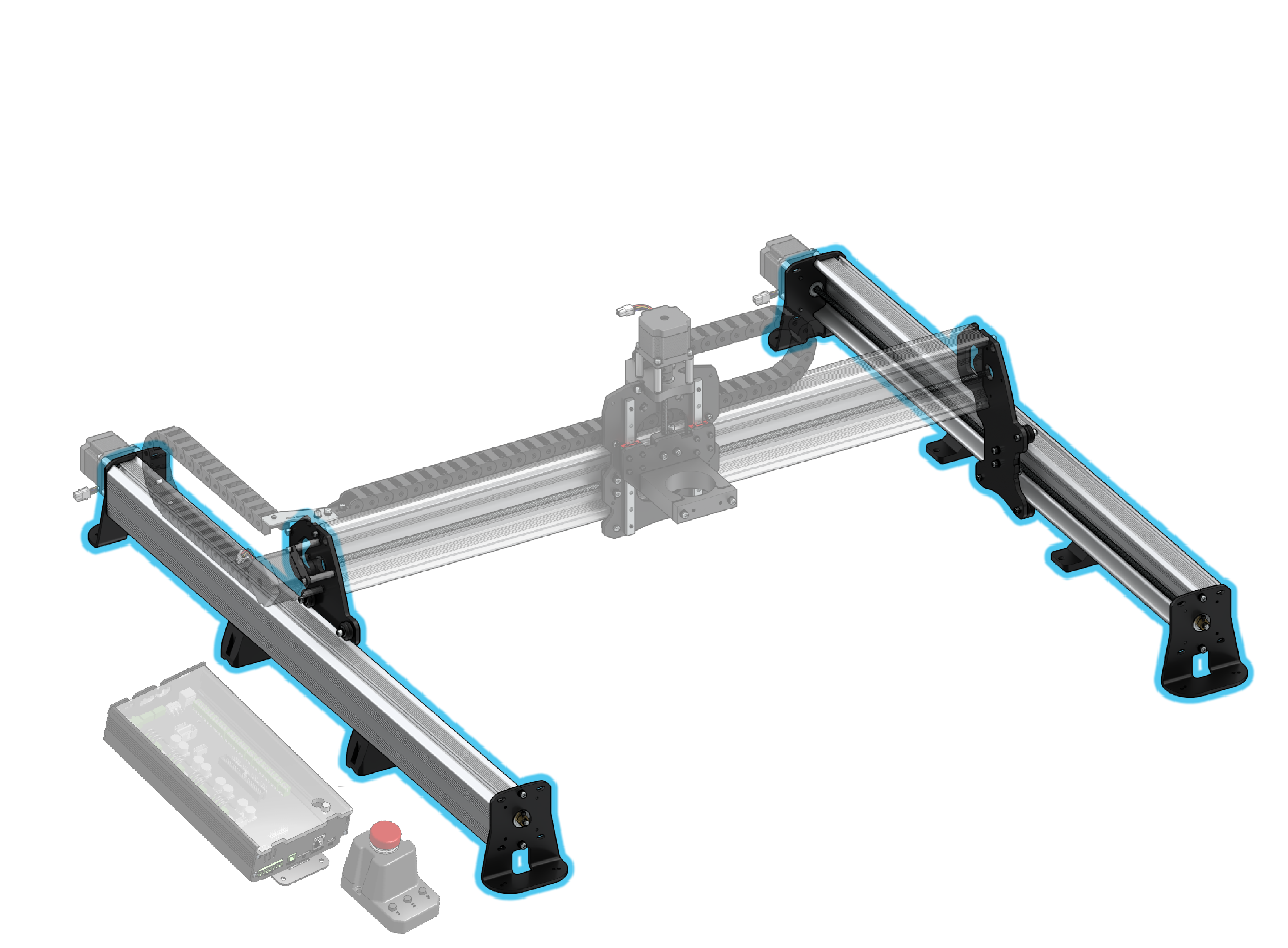
At this point of the assembly process we will begin using hardware from the yellow bag in addition to the green bag. The 3D printed middle feet will be alongside the hardware bags and note that 12×30 LongMills will have shorter Y-axis rails than pictured.
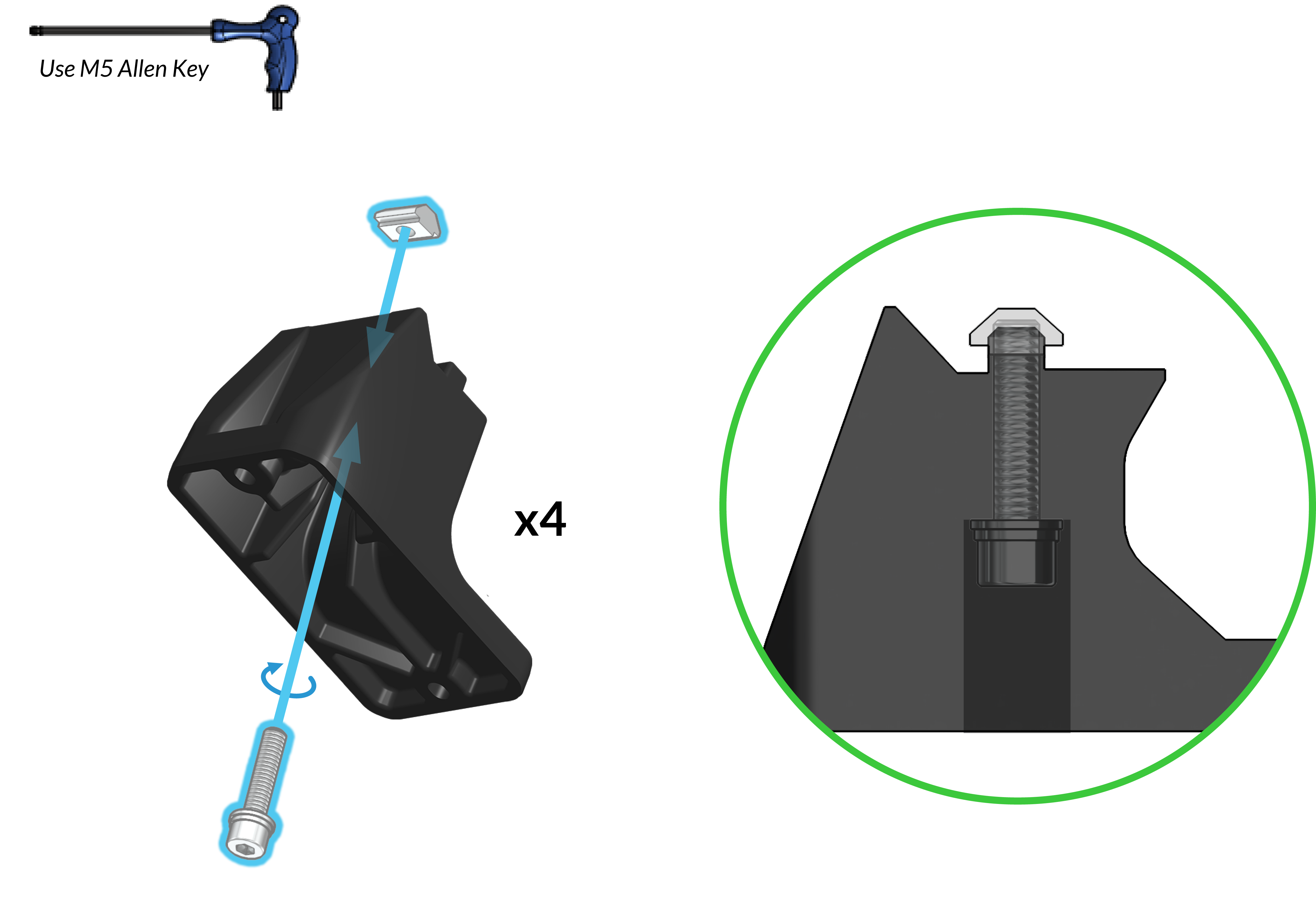
From the yellow sticker bag, grab four t-nuts. For all four middle feet, insert M5-25mm bolts through from the underside and turn them 2 turns with an M5 Allen key into the t-nut from above. The t-nuts won’t rest naturally yet because they are initially being held up at a particular spot to allow the feet to slide into the rails more easily. If you feel even a slight increase in resistance stop turning the bolts.
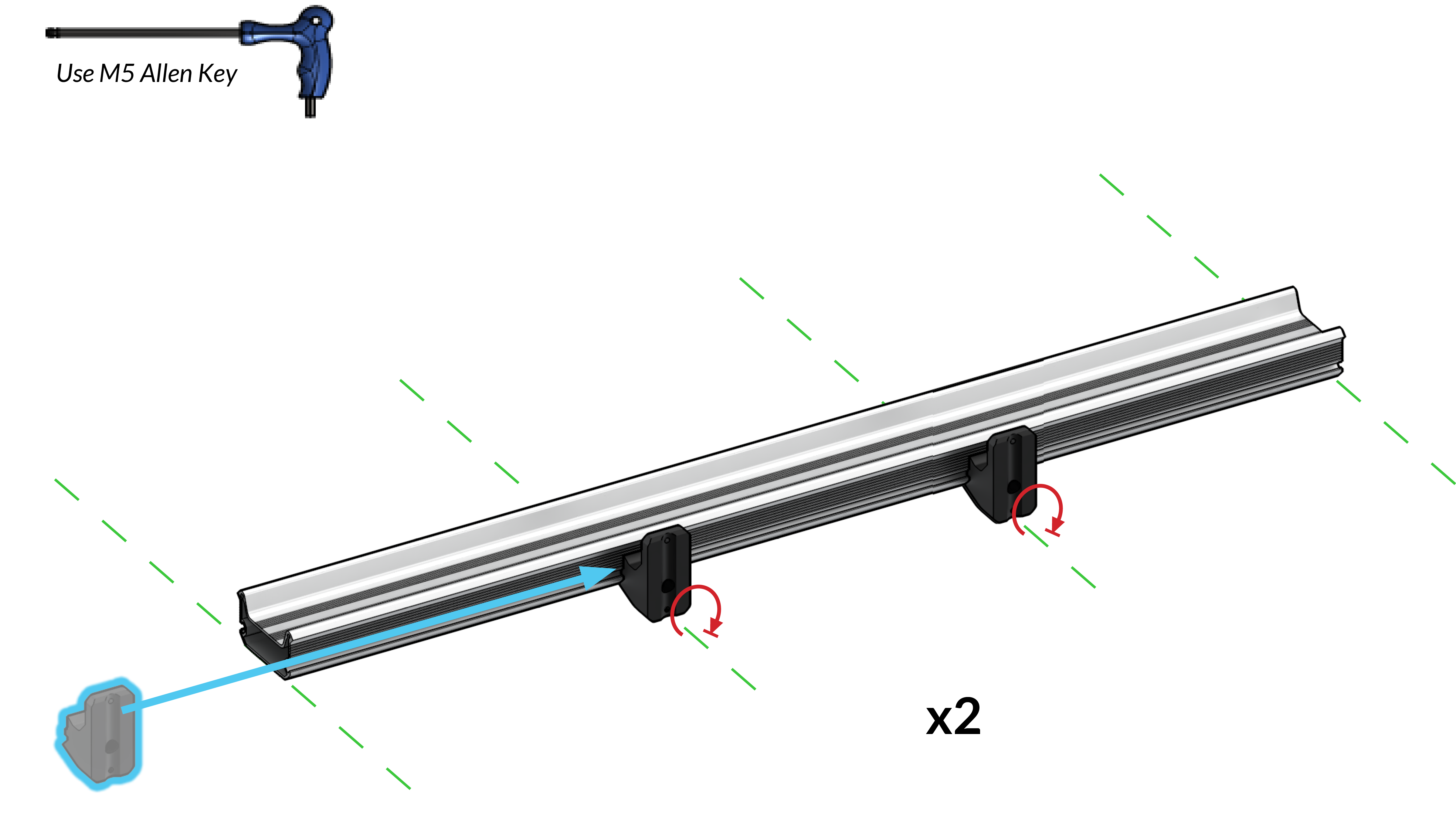
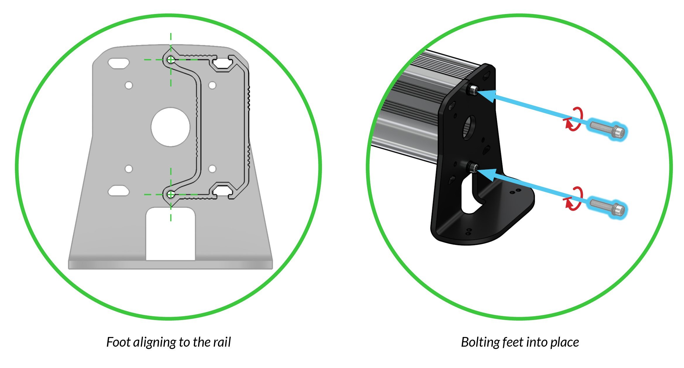
Slide in two feet assemblies through the slots of each Y-axis. Position them about ⅓ from each end then tighten the M5 bolts at the bottom of each foot to secure them into place.
INTERMISSION
From this point onward until the completion of the Y-axis rail assemblies, we will only show the steps for the right Y-axis rail. While you are assembling the right Y-axis rail, complete the steps again for the left Y-axis rail.
The following icon will be shown on each page where you should be repeating the steps for the second rail, but mirrored.

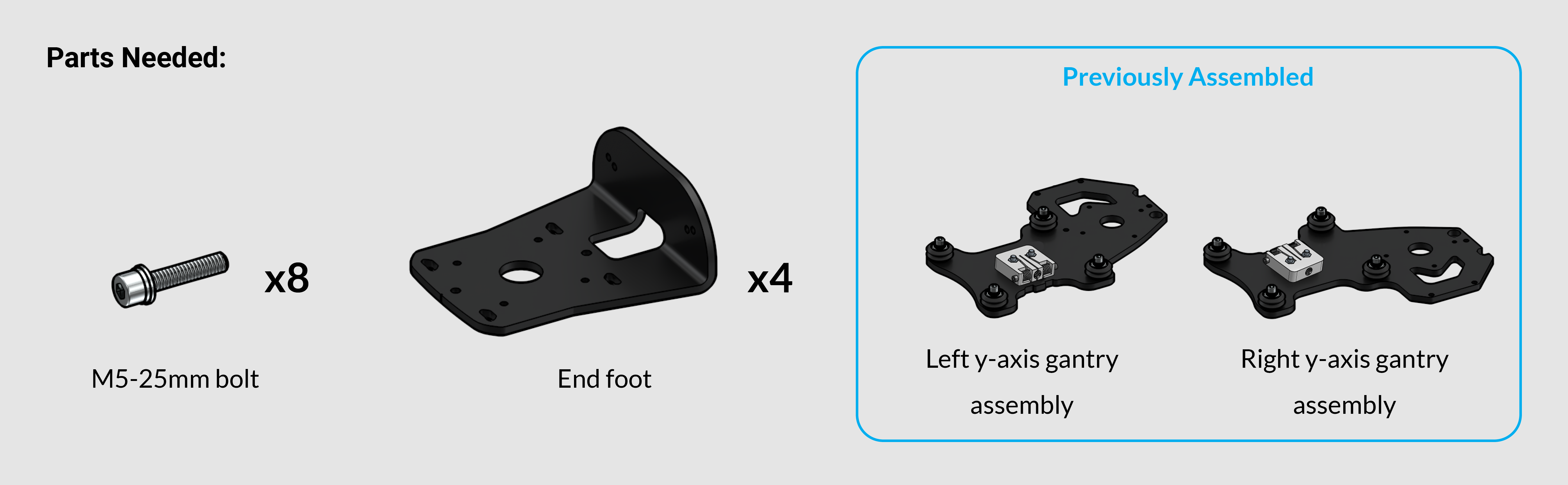
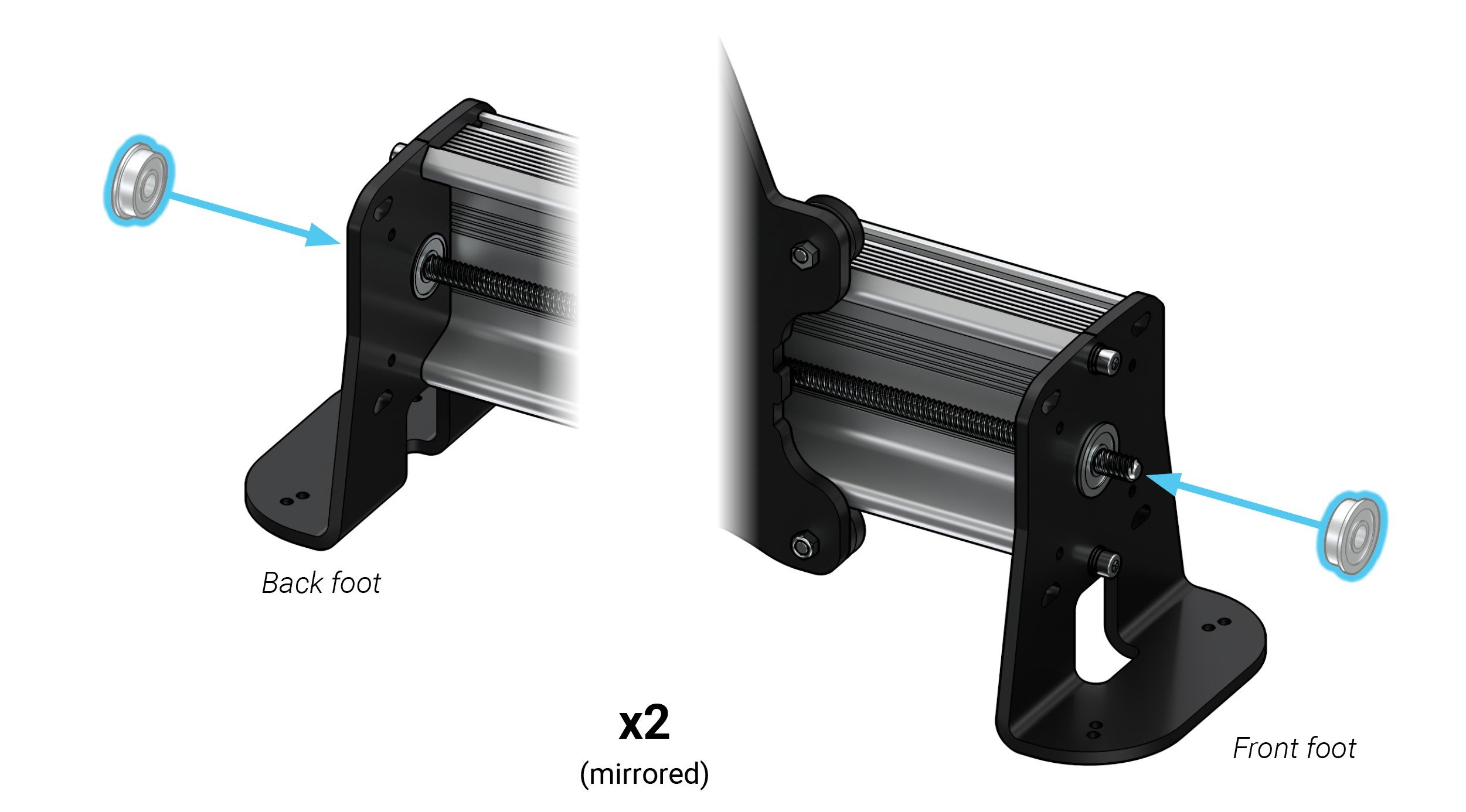
 Y-axis End Feet
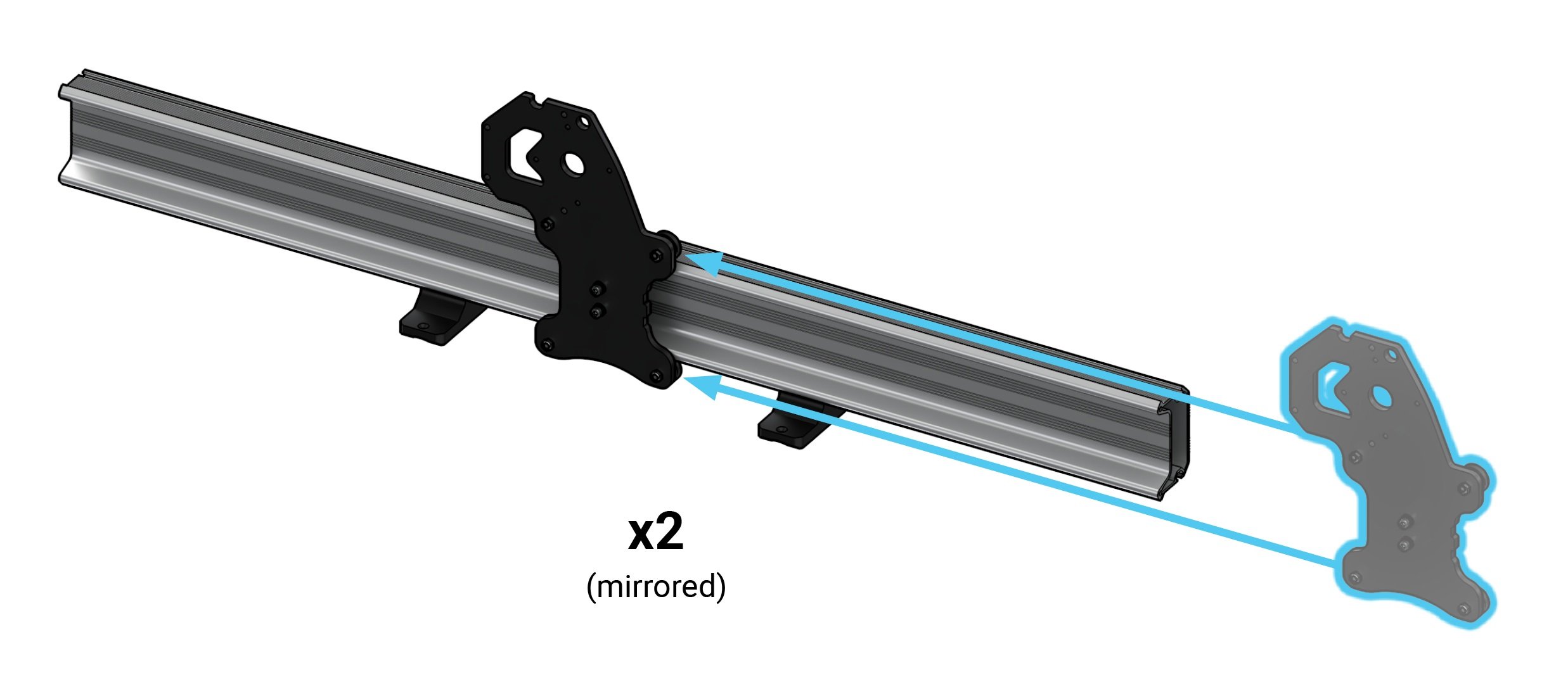
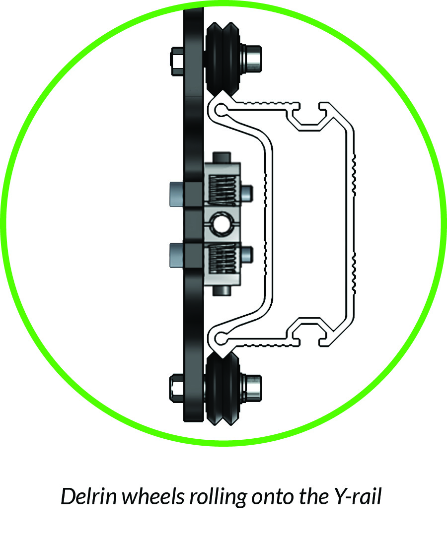
Slide the Y-gantry plate onto the Y-rail. The v-wheels should sit on the pointed edges on each side of the Y-rail (pictured).
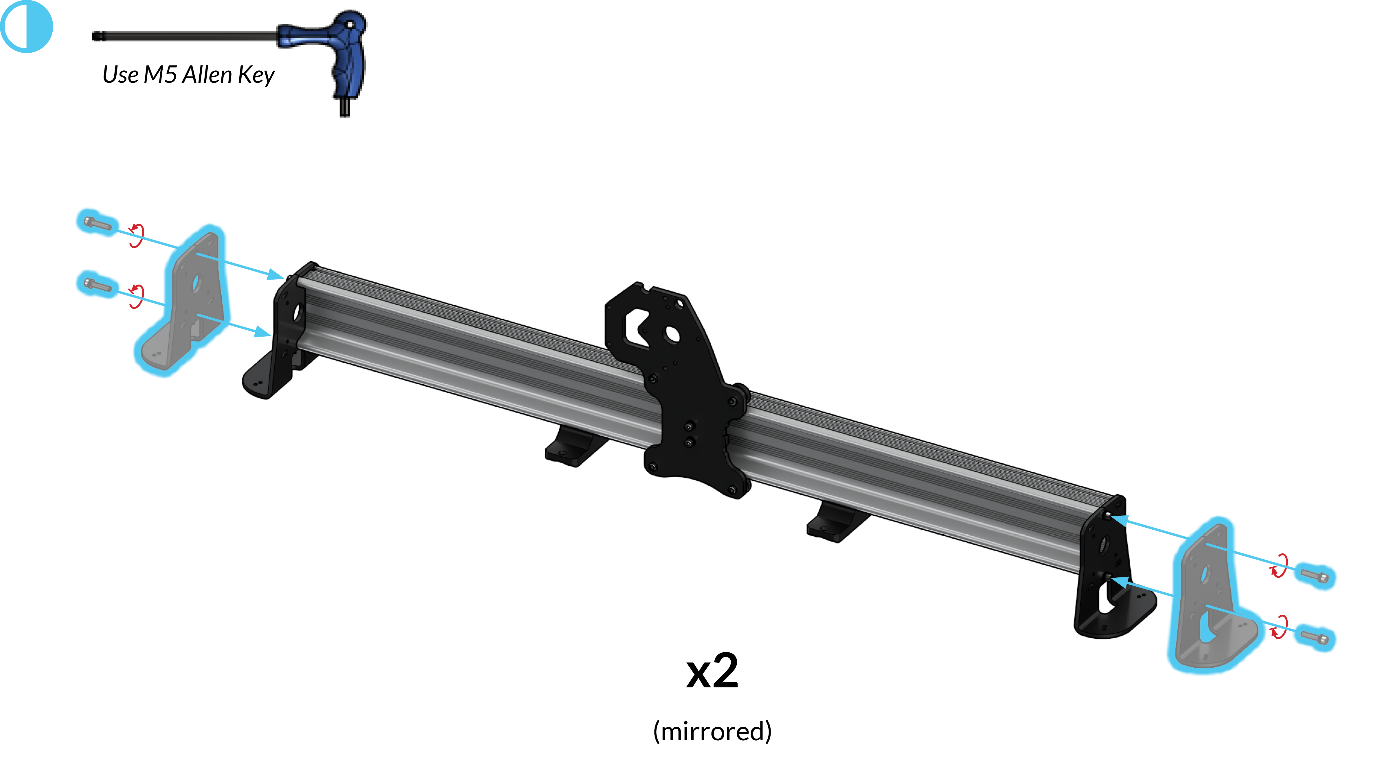
Finding all 4 steel end feet in a cardboard wrap, attach two end feet onto each end of the Y-axis rail using two M5-25mm bolts for each foot. Remember to be mirroring these steps for the other Y-axis rail.
Y-axis Lead Screws
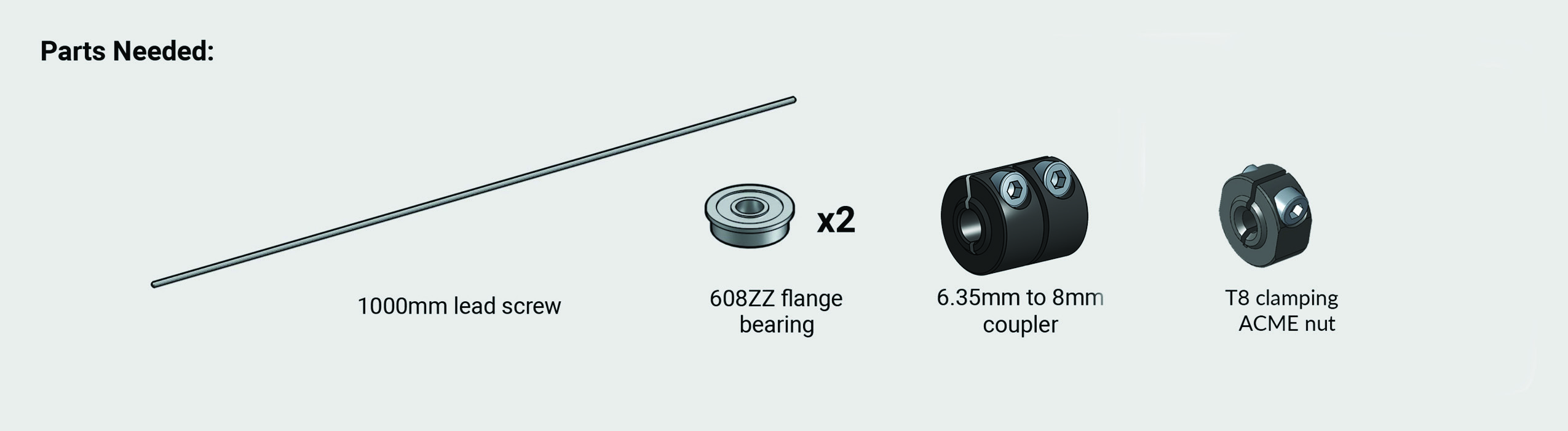
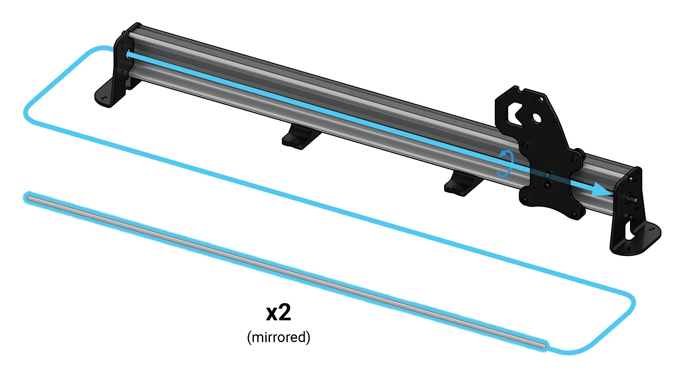
Thread a lead screw through the anti-backlash block behind the Y-gantry (for the 12×30 this will match the length of the rail). The ends of the lead screw should be able to rest in the big holes on both steel end feet.
If you find that it’s difficult to thread on, ensure you’re bringing in the lead screw from the right direction (pictured). If you remember, the anti-backlash nuts have a little arm on them and you can also try reaching between the steel Y-gantry and the rail to reach the nut and wiggle this arm to assist in threading the lead screw on. Worst case, remove an end foot and roll the Y-gantry back off to check the anti-backlash nut for burrs and debris and try threading on the lead screw again. You can also try swapping to the spare block if needed.
Insert one flange bearing onto each end foot from the outside, making sure the lead screw goes through the bearings. This fit may be tight so just do your best to hold everything in place and try to wiggle the lead screw or tap it with a mallet if needed.
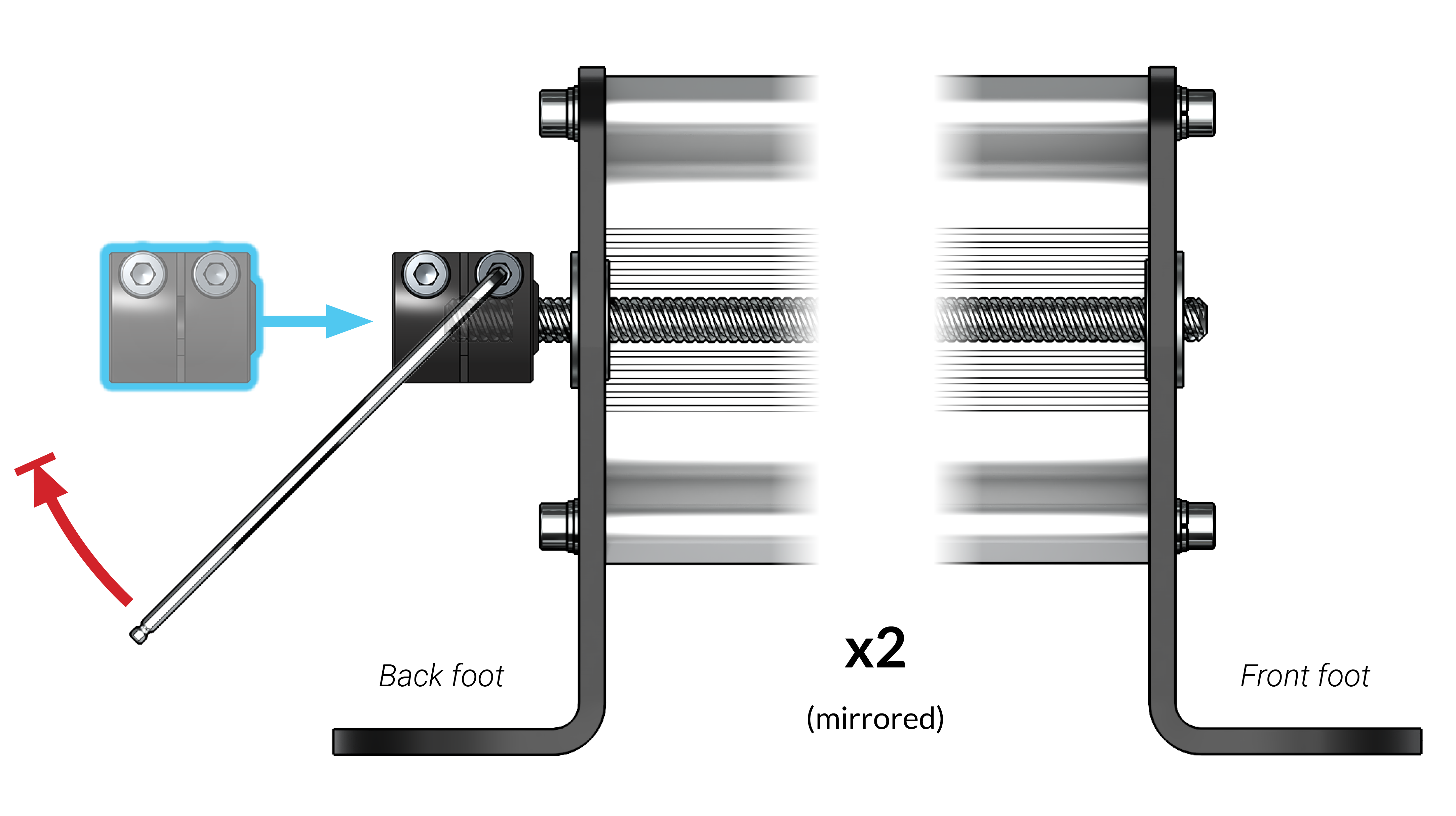
Identifying the back end foot, slide the coupler on until it bottoms out on the lead screw. Firmly secure the coupler at the set screw using an M5 Allen key. Remember to only tighten ONE of the set screws – the one on the lead screw side (as pictured).
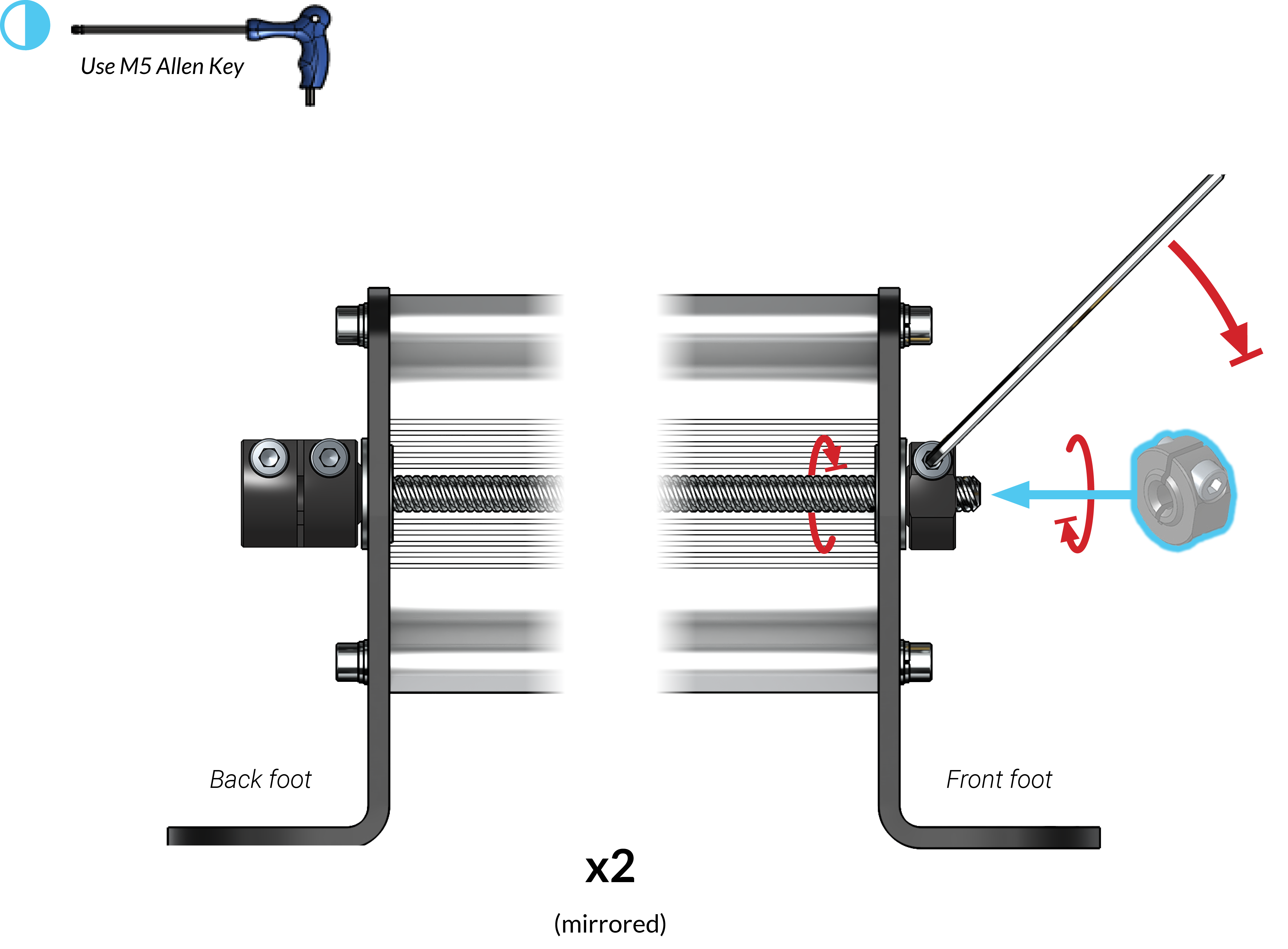
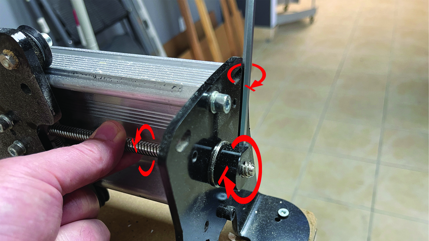
At the front, use both hands to thread a locking ACME nut into the lead screw so that it pulls it flush to the flange bearing and brings the coupler flush against the back foot flange bearing. While holding this tension in place, firmly tighten the set screw on the ACME nut. This makes another ‘bolted sandwich’ where everything should be touching bearings (as pictured) and the lead screw should only be allowed to rotate, and not move in-and-out.
You should now have two Y-axis rail assemblies! They should be a mirror copy of each other.