
The SLB-EXT is a variation of the SLB (SuperLongBoard) CNC controller, which both run grblHAL firmware. The main differences can be summarized as:
- SLB-EXT supports closed and open XYZ loop motors (with external drivers), SLB only supports open loop XYZ motors
- SLB-EXT requires 48V, SLB requires 24V
- SLB-EXT can run dual homing, SLB cannot
For full documentation of SLB and SLB-EXT capabilities, visit our SuperLongBoard resources page here.
If you’d like to know more about the sending software and firmware used with the SLB platform, please follow the links here to the SLB resource pages
Below are key details you should know about the SLB-EXT.
Board Schematic
You can download the PDF schematic layout of the SLB-EXT here
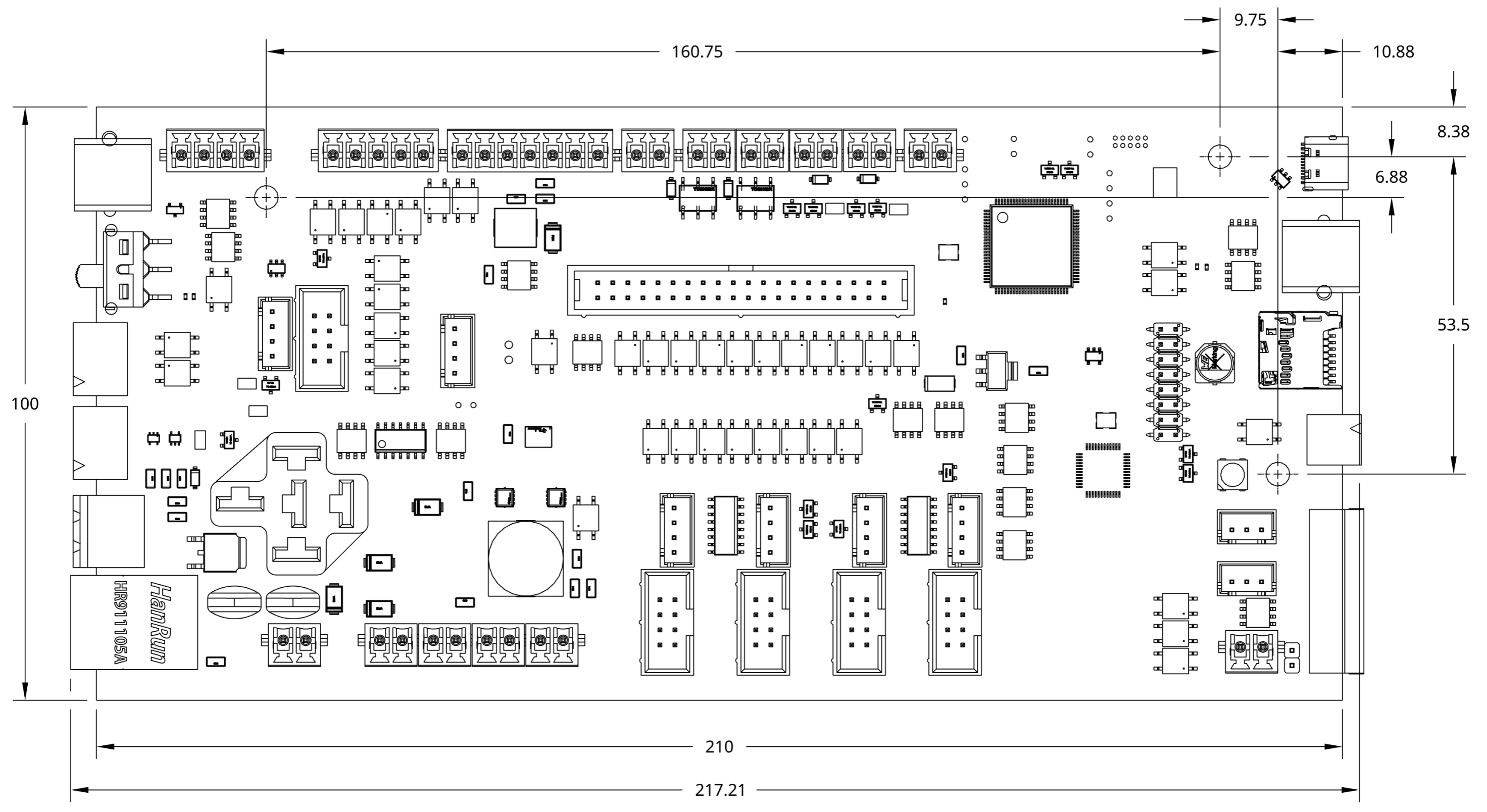
See overall dimensions of the SLB-EXT below:
Board Pinout
The SLB-EXT needs a 48V, 12.5A power supply to correctly run all stepper motors at their rated current alongside the other onboard accessories. The board can also support 36V power, should that be necessary.
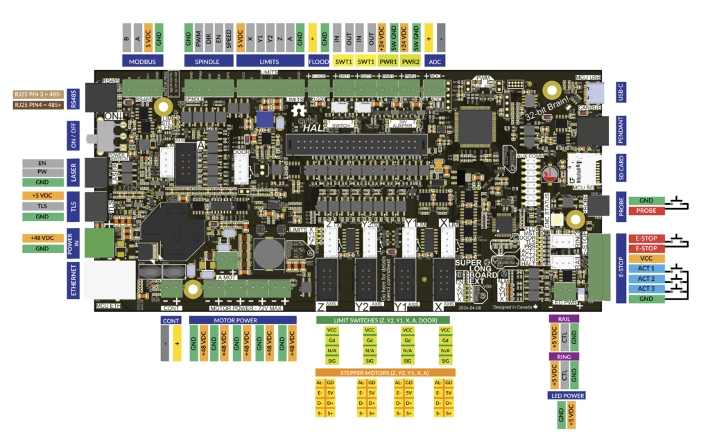
Downloadable PDF of the pin layout
Connectors List
The SLB-EXT comes with many inputs and outputs that are easy to wire in for CNC customization and accessory hookup by using pluggable terminal connectors. There are also a handful of other connectors used that are common and widely available for purchase. Below lists all connectors used on the board (male) with example links:
- Power in: 2-pin 5.08mm pitch Pluggable Terminal Block (x1)
- X, Y, & Z-axis Motor Signal: 2×4-pin 2.54mm pitch Female IDC Flat Ribbon Cable Connector (x4)
- Motor Power: 2-pin 3.81mm pitch Pluggable Terminal Block (x5)
- E-stop, AUX Limits: 7-pin 3.81mm pitch Pluggable Terminal Block (x2)
- Touch Plate, Flood out, Switch, Aux Power, LED Power, ADC: 2-pin 3.81mm pitch Pluggable Terminal Block (x8)
- RGB LED Strips: 3-pin 2.5mm JST XHP (x2)
- XYYZA Limit Switches, Door: 4-pin 2.5mm JST XHP (x6)
- Laser, TLS: 3-pin 3.81mm pitch Pluggable Terminal Block (x2)
- Spindle: 5-pin 3.81mm pitch Pluggable Terminal Block (x1)
- RS485: 4-pin 3.81mm pitch Pluggable Terminal Block (x1)
- Aux Spindle, Pendant: RJ25 Phone Jack
- A-axis: 2×4-pin 2.54mm pitch Female IDC Flat Ribbon Cable Connector (x1)
- AUX COMM Header: 40-pin 2.54mm pitch GPIO Cable (x1)
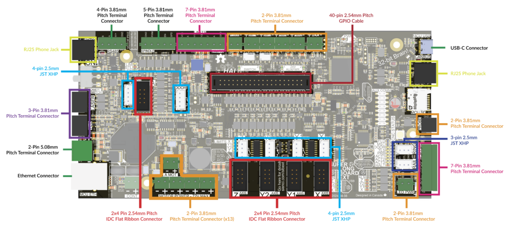
Downloadable PDF of connector list
Powering On the Board
As a good rule of thumb, leave the power switch off (slide it UP to be in the OFF position) prior to plugging power in.
When first powering on your machine using the power switch, the machine’s motors will not immediately receive power. The SLB-EXT controller is equipped with a latching emergency stop switching circuit. This is a safety feature to ensure when the controller is powered off or loses power, the machine will not instantly be powered on when power is restored. The machine will also remain in a locked ‘halt’ state and not allow any command movements in this state. To enable power, simply press the E-stop button, then release the E-stop button once.
The E-stop is designed to instantly cut power to your machines stepper motors and also send a signal back to the MCU to disable all other accessories that your SLB controls. Use the E-stop when there’s a hazard during carving and you need to immediately stop the machine. Press down on the E-stop to engage it and twist it clockwise (follow the arrows) while pulling up to disengage it.
The E-stop button unit also features customizable action buttons to control your machine. Read more about how to set these up in the SLB resources page here: Action Buttons
Motor Control
Unlike the regular SLB controller which has its own integrated motor drivers, the SLB-EXT controller is designed to control external motor drivers. In the case of the AltMill, these external motor drivers exist on the motors themselves. There are two connections being made between each motor and the SLB-EXT controller.
First is the supply of 48V DC power that powers the motor’s drivers. This connection has two cables, with the red being positive and black being negative.
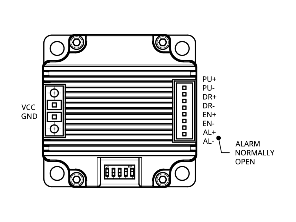
Second is the signal connection made between the board and each motor driver. These signal connections utilize differential signals with twisted pair cables to ensure maximum signal reliability. There are four key connections (using two cables each) which do the following:
- STEP/PULSE is used to instruct the motor driver how many small steps or increments to spin
- DIRECTION is used to instruct the motor driver which direction to spin
- ENABLE is used to either enable or disable the motor. When the emergency stop button is pressed, all motor drivers are disabled as a redundant safety mechanism in addition to cutting power to each driver. In normal operation, all motors are always enabled to ensure the machine’s position cannot change due to outside forces such as gravity, cutting forces, or being bumped into.
- ALARM is used by the motor driver to let the controller know that an error has occurred and the machine’s motor has lost its position. When this happens, the controller will flash an ‘Alarm 10’ and perform an emergency stop to prevent any possible damage. This will not happen in regular use, but if the machine somehow ran into an obstacle (or itself), the motor(s) involved will shut itself off and send this alarm signal. If this happens, please see our troubleshooting guide Alarm 10 – Motor Troubleshooting
Motor Specifications
Below are the motor specifications for the AltMill machines.
The closed loop stepper motor upgrade kit contains 4 of the Nema 23 1.2NM motors only.
| X & Y Axes Motor | Z Axis Motor | |
|---|---|---|
| Type: | Nema 23, 2.0 NM | Nema 23, 1.2 NM |
| Model No. | 57NYB76 | 57HYB56 |
| Voltage: | 48VDC | 48VDC |
| Frame Size: | 57mm | 57mm |
| Length: | 76VDC | 56VDC |
Motor Pinout
Homing & Limit Switches
The SLB-EXT is set up for ‘Dual homing’, which allows the machine to automatically square its X and Y axes to one another, through two limit switches on the left and right of the Y-axis. It’s important that you plug in the matching limit switch and motor cables to their corresponding Y-axis plug. A motor and limit switch mounted on the left side of your machine should both be plugged into ‘Y1’, or ‘Y2’, and not mixed between left and right.
The SLB-EXT also comes pre-enabled with hard limits and soft limits. Hard limits will immediately stop the machine if the machine runs into proximity of any of the inductive sensors on the X, Y, or Z axes. Soft limits will prevent the machine from traveling beyond its preset maximum travel distances. These distances can be changed in the ‘firmware’ settings window, and either of the limits can be turned off fully if desired.