
Basics of a CNC Machine
Know the names for the common, fundamental parts and mechanisms that make up a CNC.
Axis – The number of unique directions of movement that the CNC is capable of moving in. Most traditional CNC routers are 3-axis, comprising of the left-right (X-axis), forward-back (Y-axis), and up-down (Z-axis) directions. The addition of a rotary axis allows for cutting in a rotational direction, like a lathe.
CNC – Put simply, a machine that is designed to be precisely controlled by a computer.
Collet – A flexible steel sleeve that fits within routers and spindles. These grab onto whatever cutting tool you’re using in your CNC so that you can change between tools easily. The AltMill uses ER16 collets.
End mill / Bit – The sharp cutting tool used in a CNC spindle or router. There are many types that you’ll find, each suitable for a different application (see: The Cutting Process).
Drive system – The components of a machine that provide motion and power, enabling the spindle to cut through material. Some components of a typical CNC include motors, bearings, couplers, belts, pulleys, lead screws, and ball screws.
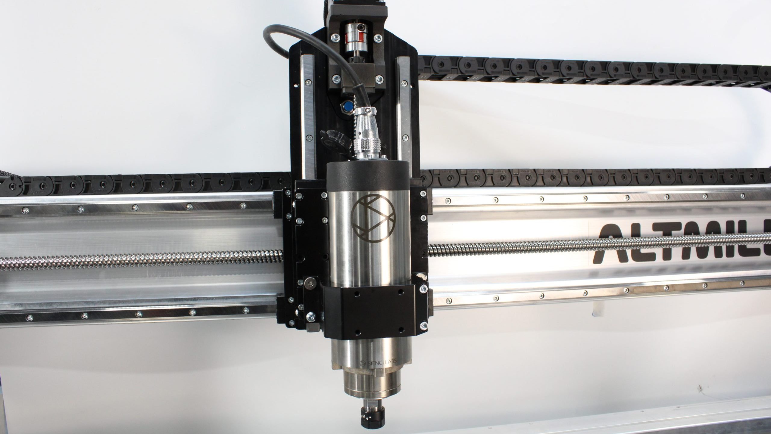
The AltMill uses closed loop stepper motors, couplers, and ball screws as part of the drive system
Dust shoe – A specialized vacuum attachment used to funnel sawdust and other material particulates from the workpiece to the dust collection system.
Limit switch / Homing switch – Switches or sensors that are used to prevent the CNC from moving out of bounds, as well as locate the CNC’s position at any time during operation. Usually, each axis will have one dedicated switch (the Y-axis has two). To utilize limit switches, we run a process called homing, which must be done each time you turn on and connect the machine to the g-code sender. The Altmill uses inductive sensors as its limit switches.
Router – A consumer-level power tool used for woodworking. Routers can be controlled by hand, or placed into a CNC router. Due to its application, routers are usually less powerful than spindles and produce more noise, but are more cost effective for many hobby-level CNC routers.
Stock / Stock material – The material you’re going to be making your project out of. This is a cookie, slab, or sheet, that has enough material to produce the finished product.
Spindle – An industrial level power tool, typically used in high volume and precision CNC machining. Spindles are designed to run constantly. They can be controlled with a VFD (variable frequency drive), so its speed can be changed through the machine interface program. The AltMill uses a 1.5KW spindle.
Wasteboard – The replaceable top layer of a CNC table, where the stock material is mounted. This is typically a flat sheet of MDF the same size or slightly bigger than the cutting area of your CNC. It may be customized to have built-in mechanisms for holding down material, such as T-tracks or threaded inserts.
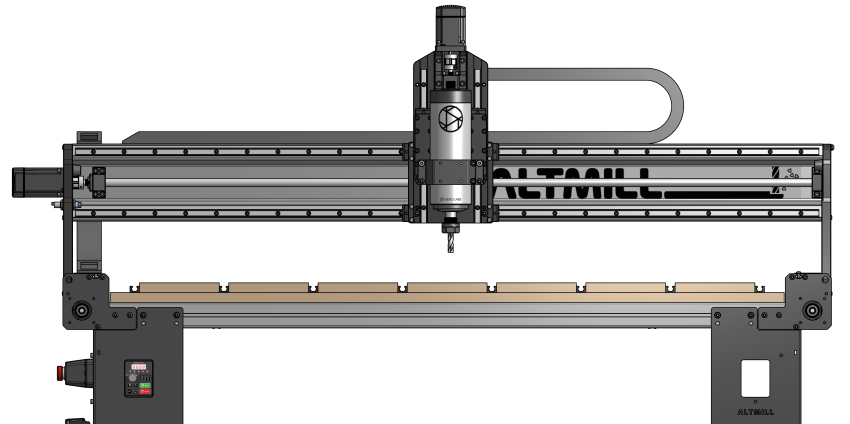
AltMill with MDF slats and T-tracks as the wasteboard
Workpiece – Similar to “stock material,” it is the starting material you are planning to cut with, or in the middle of cutting during a job.
CNC Software Terms
CAD – Computer aided design, a software program used to produce a 2D or 3D design. Also informally referred to as “design software.”
CAM – Computer aided manufacturing, a software program that converts designs into toolpaths to generate a g-code file. The program requires inputs from the user, such as feed rates, bit size and geometry, and post-processor.
G-code – The text instructions used by CNC machines to interpret and deliver commands. Many machines use g-code, not just CNC machines but laser cutters and 3D printers. There are many different languages within g-code, for various applications made by different manufacturers and researchers.
G-code sender – a software program that connects and sends g-code to the CNC machine. Features such as running and visualizing g-code files, jogging and zeroing are commonly found in g-code senders.
GRBL – A CNC g-code language used by many hobby level CNC machines, such as Shapeoko, XCarve, Onefinity and AltMill.
Machine interface – synonymous with “g-code sender.”
Post Processor – A “translator” which ensures your g-code is set to the correct language such as GRBL. This is found in the CAM software and can be changed for each g-code file. The AltMill uses these post processor
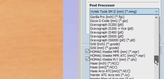
Selecting a post processor on a CAM program
Tiling – A technique for cutting projects that are larger than the cutting area of the CNC. This requires the use of a locating system so that after cutting a portion of the stock, you can slide it into a new position and continue cutting the next portions of the project while keeping them aligned to each other.
Toolpath – The series of steps that an end mill follows to cut into your material.
Vector – used in 2D design. A vector is a line or shape that doesn’t lose its resolution, therefore you can scale it larger or smaller without affecting the quality. This is directly in contrast to images made with pixels, where if you scale a pixelated image up or down it will look grainy.
Closed vector – A vector that connects to itself, such as a circle or rectangle shape.
Open vector – A vector that is not connected to itself, such as a straight line or squiggle.
Visualizer – A program that shows the toolpaths of g-code files, illustrating how the machine will move during the job. Some g-code senders will have visualizers built-in, so you do not need to download a separate program.
Basic CAM Parameters
These are the settings you’d change to improve the performance of your cutting job, found in most CAM programs.
Cutting feed rate [mm/min, in/min or IPM] – The speed of the machine in the XY directions, not the router or spindle rotation, also called “feed rate.”
Plunge feed rate [mm/min, in/min or IPM] – The speed of the machine in the Z direction, not the router/spindle rotation, also called “plunge rate.”
Retract height [mm, in] – A setting on CAM software which defines how high the machine will move when it is travelling to a different location, not cutting.
Spindle speed [RPM] – The rotational speed of the spindle or router, not how far the machine moves.
Step down / LOC length of cut / DOC depth of cut / DPP depth per pass [mm, in] – The thickness of the cutting in the Z-direction.
Step over [%] – The offset between two toolpaths, a smaller offset means there is more overlapping which leads to better surface finish but will take more time. The offset is expressed as a percentage of the bit diameter.
CNC Operation
These actions and inputs are usually controlled using a machine interface or g-code sender program. You can think of the program as a car dashboard, containing all the buttons and actions you’d need to run your machine.
Homing – The automated process of locating the bounds of your work area through triggering limit switches in all axes. Homing should run when you connect to the machine, in order to establish limits from the get-go. It is helpful for locating the machine in scenarios of a power outage or advanced job setups.
Job / Cutting job – The process of cutting out a design by running a g-code file on the CNC. This file can sometimes be composed of multiple toolpaths.
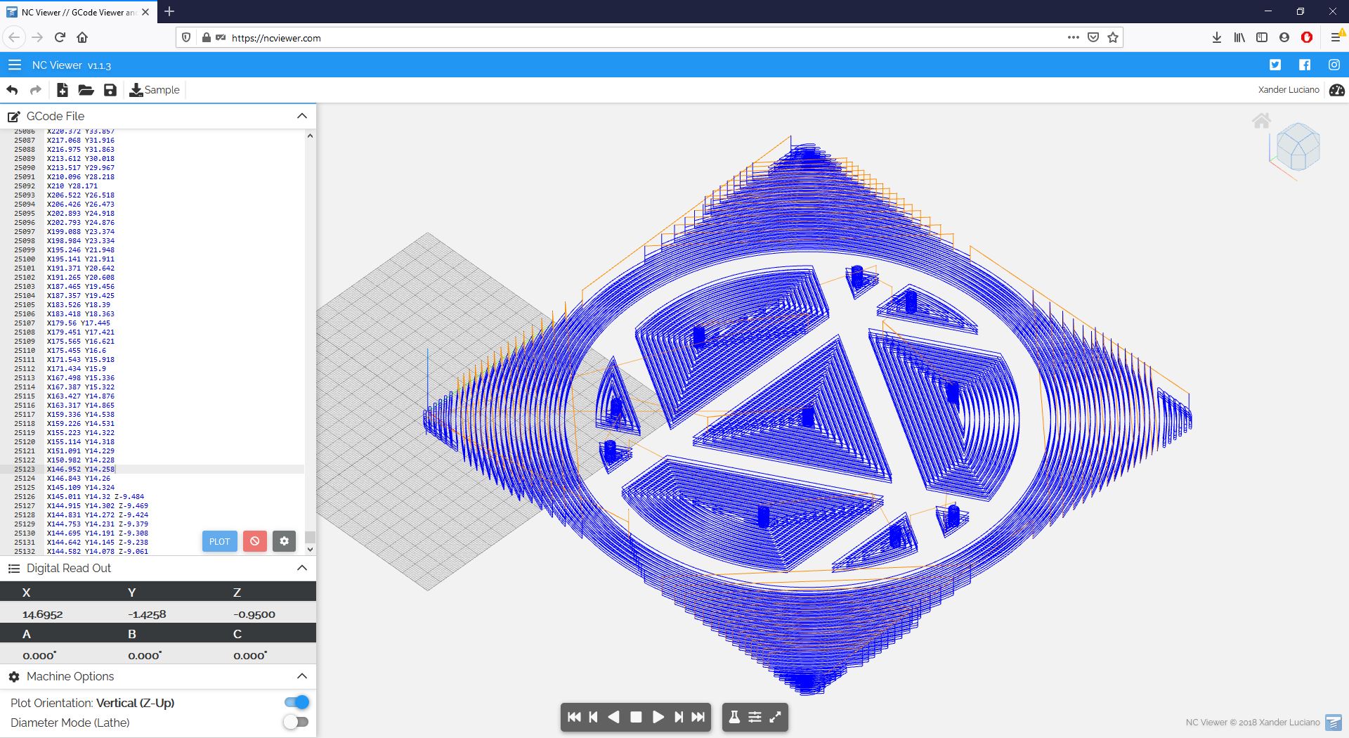
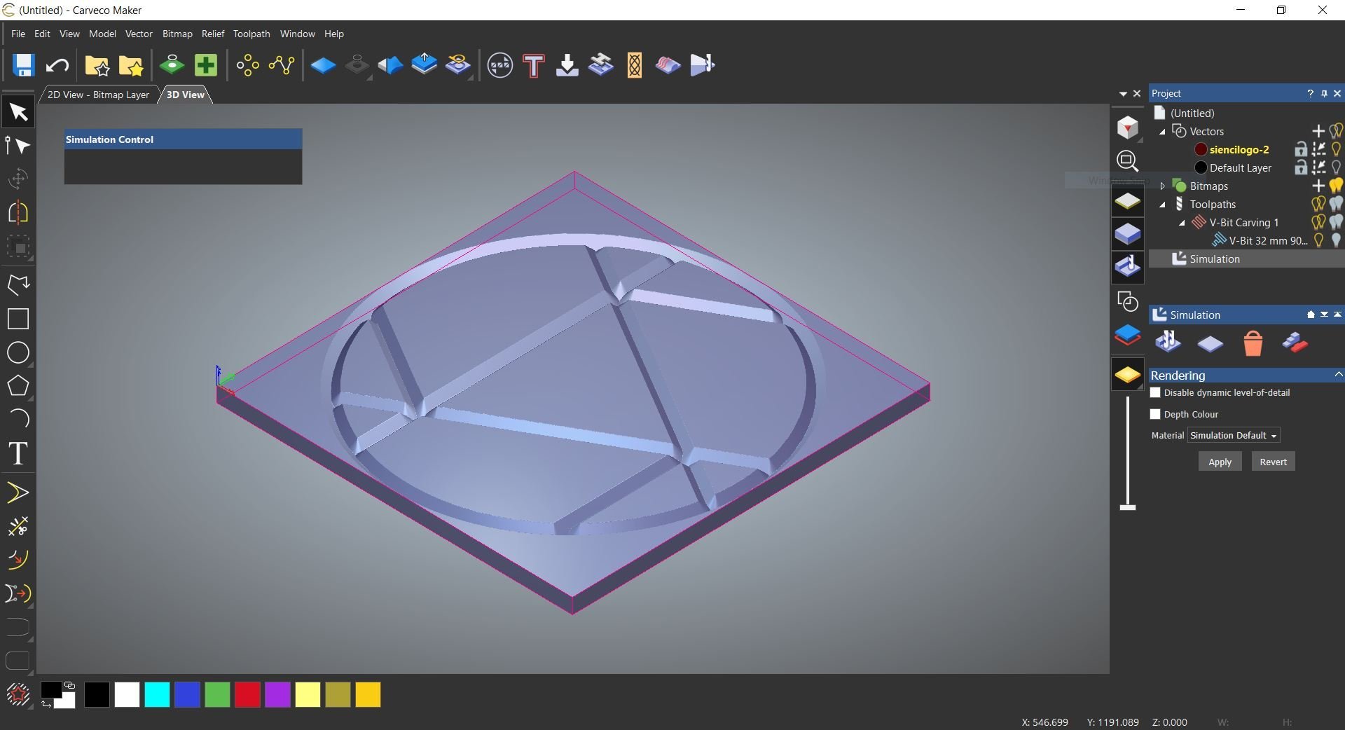
Toolpath of Sienci Labs logo on NCViewer
Jog – The act of moving the machine using manual buttons and controls (not pre-defined in the g-code file). Typically we jog to get the machine to an optimal place before running a job, zeroing or homing the machine.
Limits – These are the boundaries of where the machine can move to. There are two methods for setting limits; first is through “soft limits” which use the maximum travel values ($130, $131, $132) in the firmware to figure out if you are moving outside of boundaries. The second is through “hard limits” which use physical limit switches to detect the machine position. These methods can be used together, and will produce alarms to your g-code sender whenever the machine exceeds these limits.
Origin / Zero – The reference point of your cutting job, anchoring your digital design into the real world. The zero is usually set at the lower left corner, top surface of your material, but can be changed in the CAM program. Once the g-code has been created with this zero, you should zero the machine at the same relative position on the workpiece, so that the job runs in the expected area.
The zero is usually indicated by a coordinate axis, as shown on the CAM program (Carveco Maker)
Probe – A process to automatically set the zero or origin on the stock material so you can run the job at the correct location. This process is set up on the g-code sender, and uses a conductive tool called a touch plate.
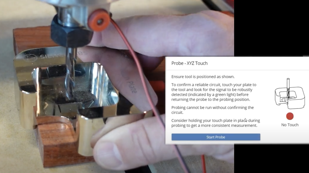
Probing using the AutoZero touchplate on gSender
Surfacing – A job specifically used to flatten a piece of material. This can be a wood slab or the wasteboard itself, done during machine setup or maintenance to keep it level to the CNC’s mechanics. Typically you use a surfacing bit which has a larger cutting diameter.
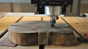
Surfacing a slab using a specialized surfacing bit
Tool change – A process used to switch between cutting bits either during a job or between jobs. This allows for much more elaborate projects to be made.
Tramming – A method used to adjust the router or spindle to cut exactly perpendicular to the bed of the CNC machine. This is an optional practice done at the beginning of the machine setup or during maintenance to make straighter cuts and reduce grooves in flat surface cuts.
The Cutting Process
Cutting away material on a CNC is affected by two major factors:
- The type of cutting tool that’s being used, which includes its shape and size.
- What cutting approach is being used when moving through the material; an analogy would be cutting across the wood grain versus along it.
Tools and Features
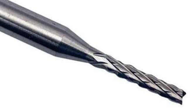
End mill – Bits with spiraled flutes, which can come in with many different tip shapes.
Flute – A groove on the cutting bit to allow for material to be ejected. Bits can have more than one flute, which increases the surface area of contact with the material.
Round groove / Juice groove / Bowl cutting bit – Has a semi-circle profile, which works well for carving rounded profiles.
Surfacing bit – Has a large cutting diameter, used to remove large areas of material at a shallow depth. This is used to flatten out material.
Tip / Flute shape (upcut, downcut, compression, straight, corncob) – The shape of the end mill you are using, which determines its application.

From left to right: ballnose bit, flat end mill, V-bit
Ball nose bits are rounded on the tip, similar to round groove bits. They are used for reliefs and 3D carvings.
Compression bits are a combination of upcut and downcut bits, with spirals in both directions providing a clean finish and also ejecting chips from the cutting surface.
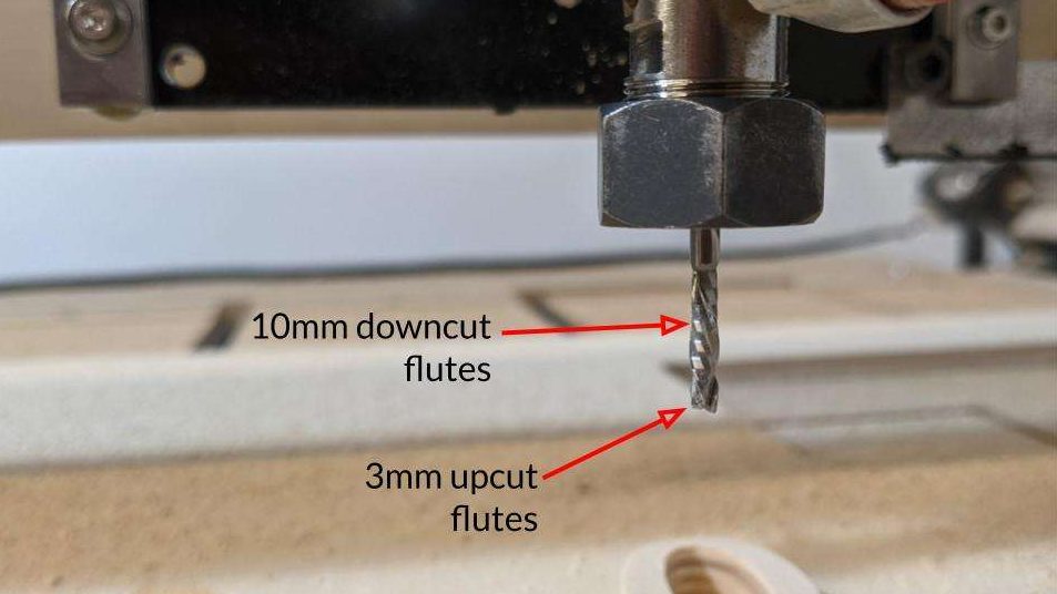 Compression bit with indication of upcut and downcut portions
Corncob bits have a unique diamond pattern which allows for abrasive materials to be cut, suitable for composite materials such as PCBs and carbon fiber.
Closeup of corncob bit with diamond pattern
Flat end mills have a square tip. They can also have spirals (upcut or downcut), or be completely straight. These are good for general purpose milling, such as cutting out borders or straight profiles.
Straight bits do not have any spirals, instead it has flat faces which run down the length of the bit. They are used for cutting plastics, woods and composite/laminate materials which are susceptible to fraying.
Tapered bits become more narrow at the tip, which allows for small details to be cut.
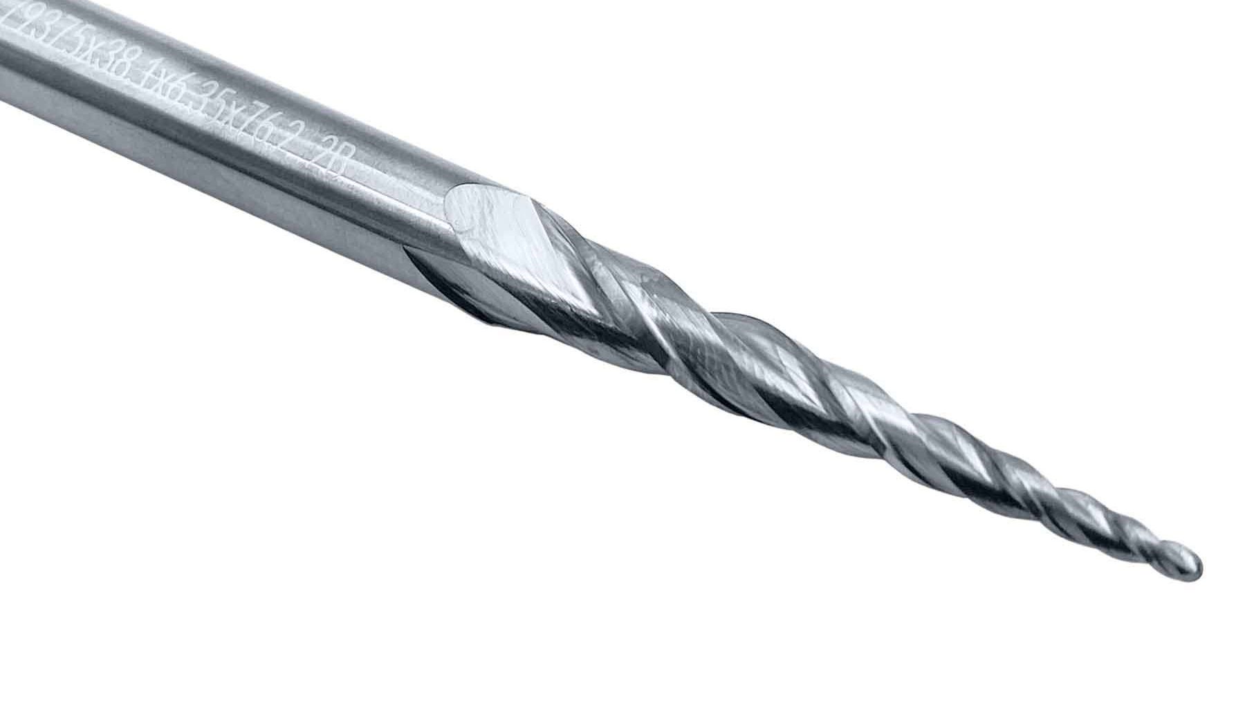
Tapered ball end mill, a combination of tapered bit and ball end mill – suited for carving curves, contours, and reliefs
Upcut and downcut bits have opposite spiral directions, causing the material to be pushed either up or down respectively. Upcut bits are best for cutting materials that can melt onto the bit, such as plastics and aluminum, since these chips can be ejected out of the material. Downcut bits can be used for woods that can splinter easily, because they push the chips down which creates a cleaner finish.
V-bit – Has a pointed tip in the shape of a ‘V’ and works great for cutting away as an engraving, making lots of different details especially for signs. They can also be used for inlays and chamfering and come in many angles such as 30°, 60°, 90°, and 120°.
Cutting Styles
Climb milling – A milling technique in which the CNC machine is moving against the router / spindle rotation. This causes more cutting forces than conventional milling, but can provide a better surface finish. If climb milling, there must be compensation used to eliminate backlash.
Conventional milling – A milling technique in which the CNC machine is moving with the router / spindle rotation. This method eliminates backlash but can reduce tool life and surface finish due to chips and material rubbing onto the tool. This is the more common milling approach, and is usually the default on CAM programs.
Finishing pass – A cutting job used to cut out the exact geometry of the design, removing small amounts of material after a roughing pass had been done.
Pass – A layer of cutting, defined by a certain thickness (step down or depth of cut).
Profile / Contour cut – A type of toolpath where the cut follows a line or the outline of a shape.
Pocket cut – A type of toolpath where the machine will cut all the material that is within the shape. Pocket cuts will only work for shapes that are closed vectors.
Ramping – A method used to start or end a cut on a workpiece; instead of the machine descending vertically (plunging) into the material, it will move vertically and horizontally to gradually enter the material at a slope. This can extend the life of the cutting bit.
Relief cut – A type of toolpath where the machine cuts raised geometries from one side of the stock material. For example, mountain terrains are considered relief cuts, because of the slopes and valleys.
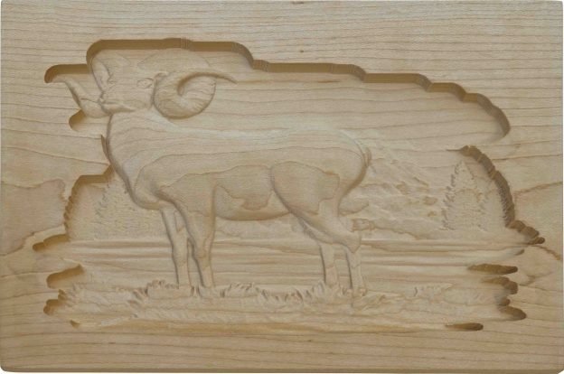
A relief of a ram
Roughing pass – A cutting job used to cut out the approximate geometry of the design, to remove larger amounts of material at once. This is usually followed by a finishing pass to clean it up.
CNC Electronics Terms
DIP switch – A component on CNC control boards which sets the microstepping of the motor.
Driver – Small electronic boards that control the motors. For the AltMill, external motor drivers are plugged into the SLB-EXT controller, whereas for the LongMill MK2, drivers are directly soldered on the SLB controller.
Electromagnetic interference (EMI) – Electrical noise or disturbance that can interrupt jobs or cause inconsistent, random behaviour on the CNC, such as stopping mid-way, changes in movement direction, and inaccurate cutting. It can come from the machine itself (spindle, motors) or the setup and environment (dust collection, electrical tools, magnets, power bar).
Firmware – The programming installed into electronics to enable basic functions, such as how to handle communications, hold external files, and store settings. Similar to an operating system of a computer.
IOT relay – A device used to automatically control power to AC powered electronics through g-code commands. Useful for controlling a router, vacuum, and lighting.
Microstepping – A way to control the accuracy of motor rotations, by breaking up motor motion into ‘steps,’ then adjusting how many steps complete a full revolution.
Sources & Other Info
https://www.cnccookbook.com/cnc-dictionary/
https://shapeokoenthusiasts.gitbook.io/shapeoko-cnc-a-to-z/glossary
https://cimquest-inc.com/what-is-chip-load/
https://www.cnccookbook.com/climb-milling-versus-conventional-milling/
https://www.harveyperformance.com/in-the-loupe/ramping-success/
http://www.helmancnc.com/g-code-g95-feed-per-revolution/
https://www.endmill.com.au/pcb-corn-cutter-carbide-router-bit/