We’re sure you’re itching to start cutting! Before you begin making chips fly, we recommend going through these final checks to ensure you are set up for success.
Mechanical
- All screws in the table frame have been tightened
- End plates with T-nuts
- End plates to Y rails
- Crossbeams to Y rails
- Levelling feet
- Legs to frame
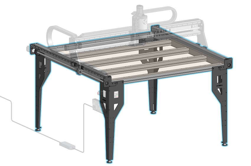
Table assembly
- All couplers have been fully tightened on both the motor shaft and ballscrew sides
- The X rail is contacting against the reference edge of the left Y gantry plate
- The back of the rail may not sit flush, but at as long as the ball screw is aligned to the motor shaft then it is OK
X rail aligned to left Y gantry plate edges
- Table is levelled by using a level tool and adjusting the feet
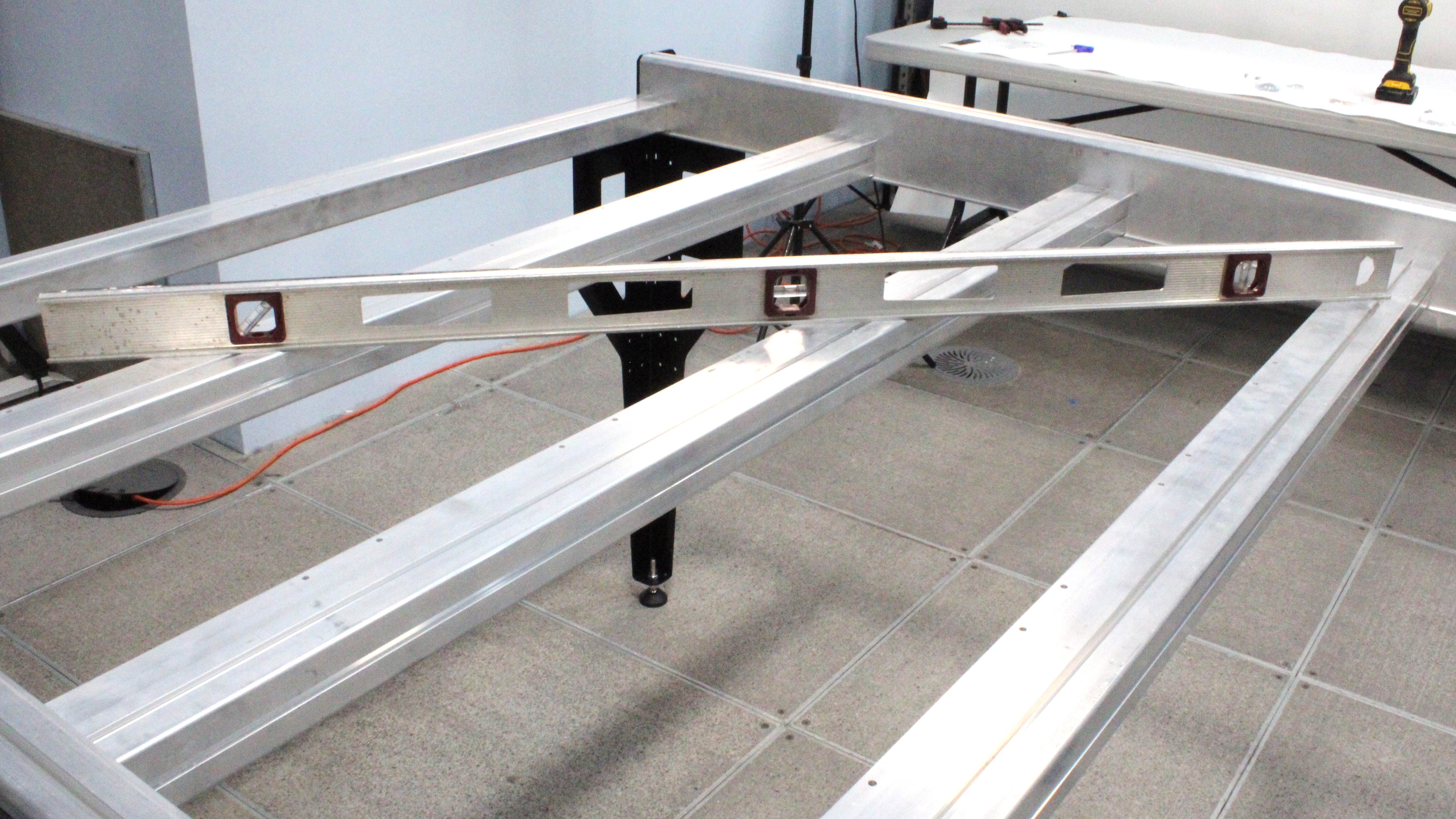
Using level tool on AltMill table frame
Electrical
- Motor DIP switch positions are correct for each axis
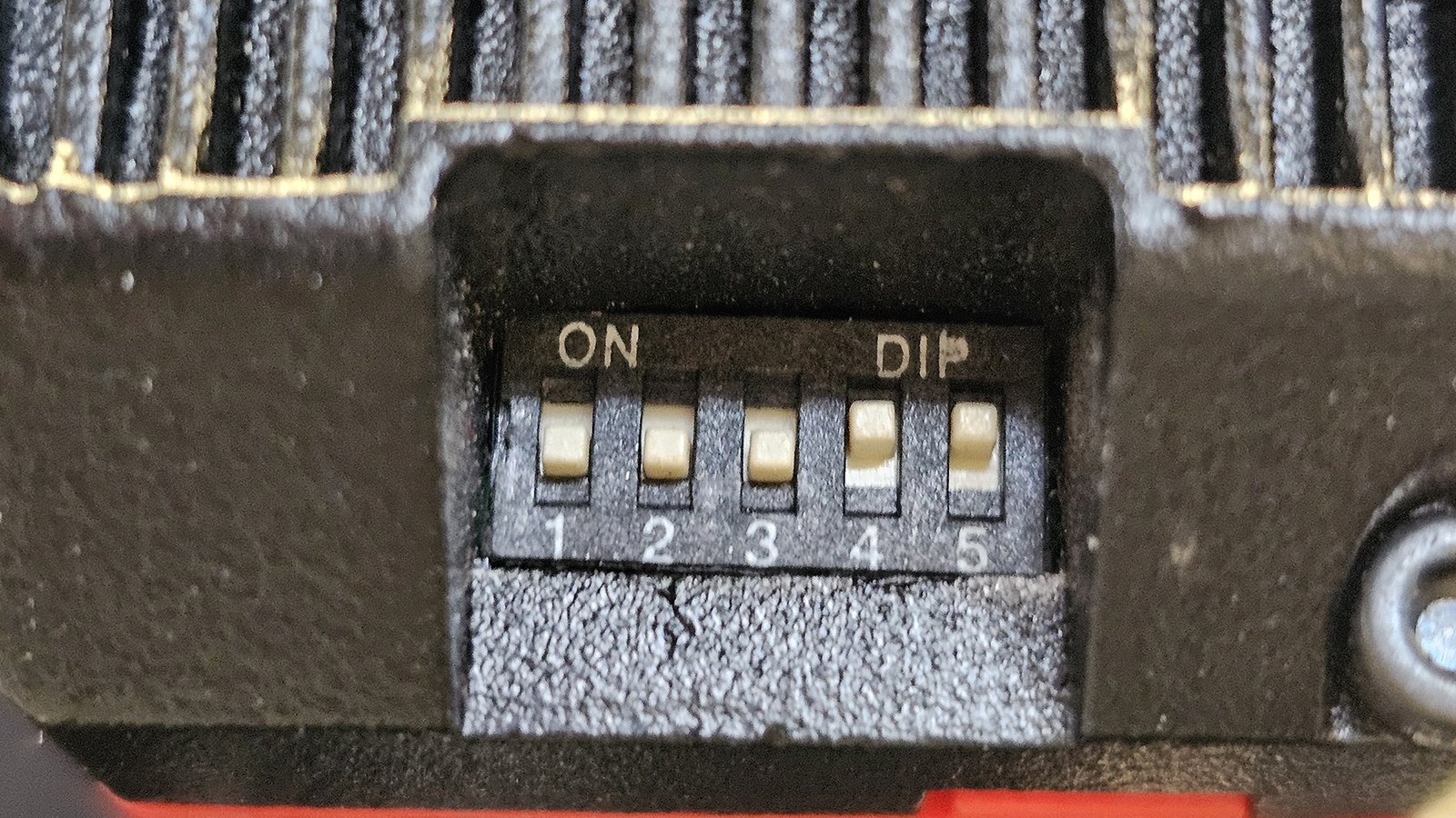
Correct motor DIP switches setting for X and Y-axis from 1-5: OFF, OFF, OFF, ON, ON
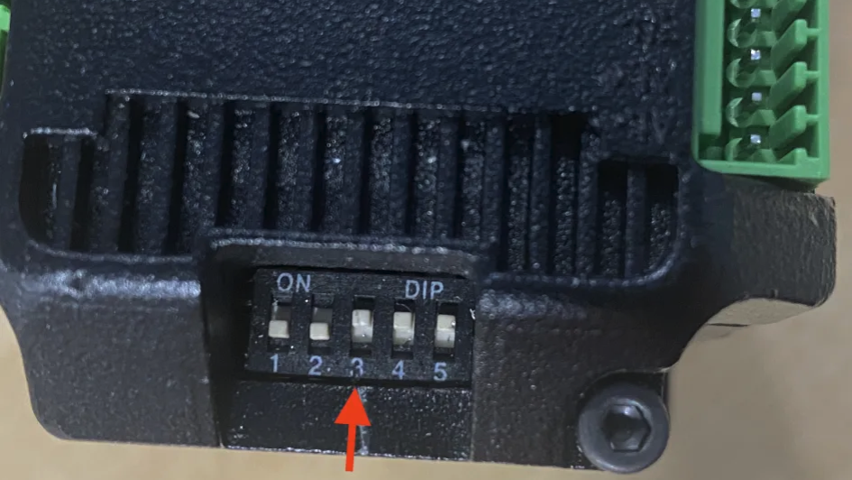
Correct motor DIP switches setting for Z-axis from 1-5: OFF, OFF, ON, ON, ON
- Motor cable wires are not frayed or detached from connectors
- If they are simply disconnected, you can use a small screwdriver to press each orange spring terminal release to insert the wire back into the terminal
- Y1 motor and sensor connections are on LEFT side of machine, Y2 motor and limit switch connections are on RIGHT side of machine
- You will get homing alarms and errors if you mismatch these connections
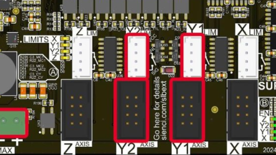
Y1 and Y2 motor and sensor connections on SLB-EXT
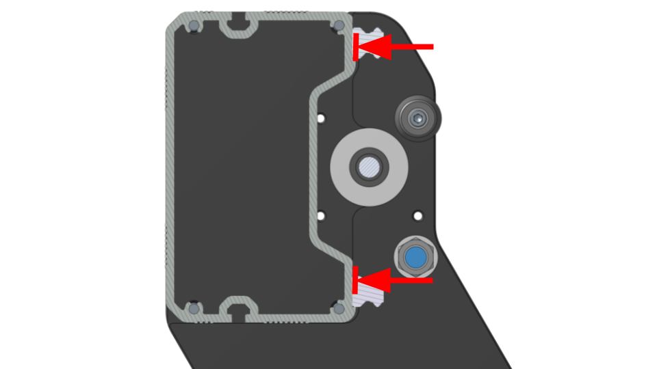
- Y-axis inductive sensors are positioned correctly, and spaced equally between the left and right
- Generally, sensors should be 1-2mm behind the bump stop but may be closer if you encounter homing alarms
- Left and right sensors should be spaced the same amount from the bump stop
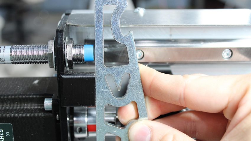
Y-axis sensor offset distance
- Z-axis inductive sensor is positioned so that it does not protrude past the X carriage surface
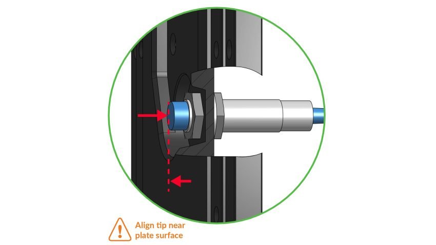
Z-axis sensor flush with X carriage
- Inductive sensors are functional
- Check by putting a metal object near the sensor face and see if a small red light triggers on the back
- Spindle VFD is plugged in to a separate 15A circuit from the SLB-EXT control board
Software
- You are using gSender version 1.4.9 or newer
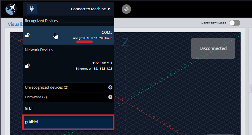
- grblHAL option is selected upon startup and connection to machine
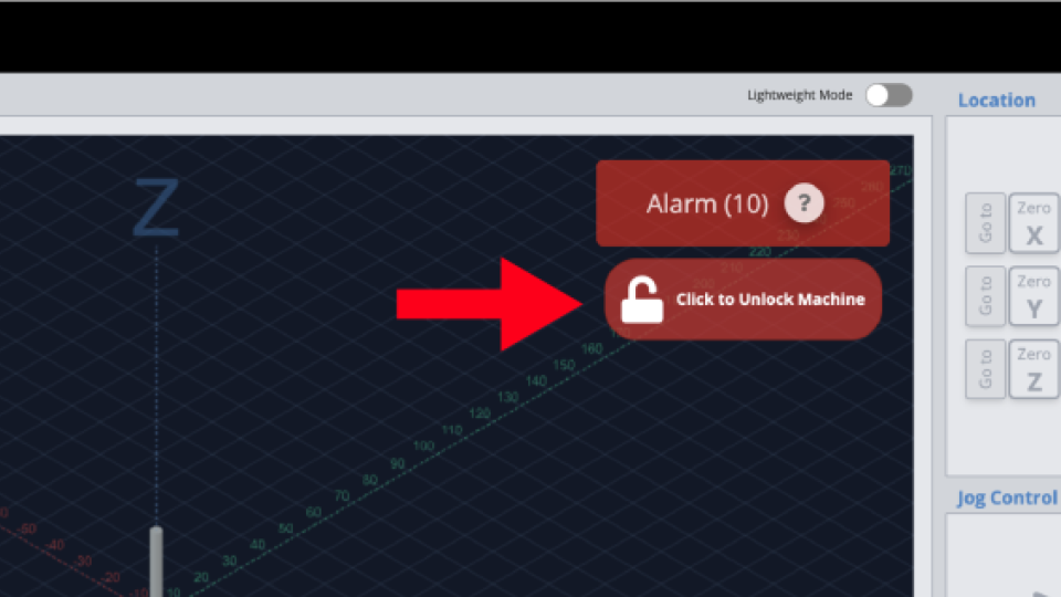
- Alarms can be cleared after pressing and releasing (turning) the E-stop button
- The machine can move in the X, Y and Z directions by using the jog control buttons
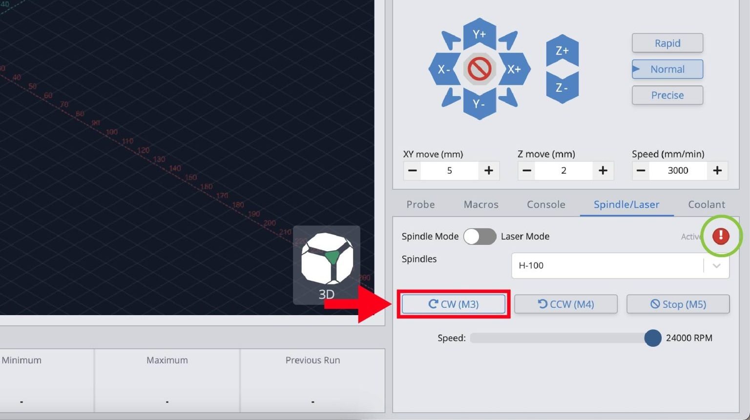
- The spindle can spin up in the correct direction, without alarms or errors, using the CW or CCW buttons. Stop the spindle, and pay careful attention to make sure it is spinning in the specified direction as it slows down to a stop.