
X-Y axis squaring
The AltMill is set up by default to use ‘dual homing’ in the Y-axis direction. This makes it possible to easily adjust the squaring of the machine in the XY directions, as well ensure the machine automatically squares itself every time the homing cycle is run.
Ultimately, if the left and right Y-axis inductive sensors are at matching positions, the machine is likely to be nearly perfectly square, but in some cases, small adjustments are needed.To figure out how square your AltMill is, you can use gSender’s built in ‘XY squaring’ tool found here: https://resources.sienci.com/view/gs-additional-features/#xy-squaring . If your machine is not square, this tool will inform you of some distance that either the left or right Y-axis gantry should be moved forwards or backward.
In the case of the AltMill, simply adjust either the left or right Y-axis inductive sensor forwards or backwards according to this amount. The next time you run the homing cycle, the machine will now automatically be squared.
Machine tramming
Tram adjustment, or ‘tramming’ (the act of adjusting this) essentially refers to the alignment of the spindle/router’s rotating axis to be perfectly perpendicular to the movement of the X-axis (usually referenced by the actual machine bed/wasteboard).
On the AltMill, tram alignment is preset by a series of precise reference edges and alignment tools through the frame and gantries. At the spindle mount, tram alignment is set by the use of two shoulder screws. Using these as a ‘default’ will generally mean that your machine should be quite well trammed, but in some cases, a small adjustment may be necessary.
Checking for tram alignment will typically be done using a tramming arm tool which holds one or two dial indicators, used to ‘sweep’ across the bed/wasteboard surface to find high and low spots. Some specialized tools such as the SST tram tool exist to make this easy, but it is otherwise possible to find a way to mount a dial indicator to the rotating axis of your spindle.
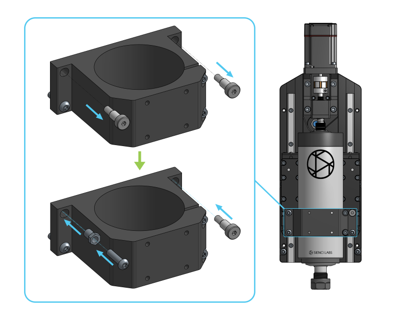
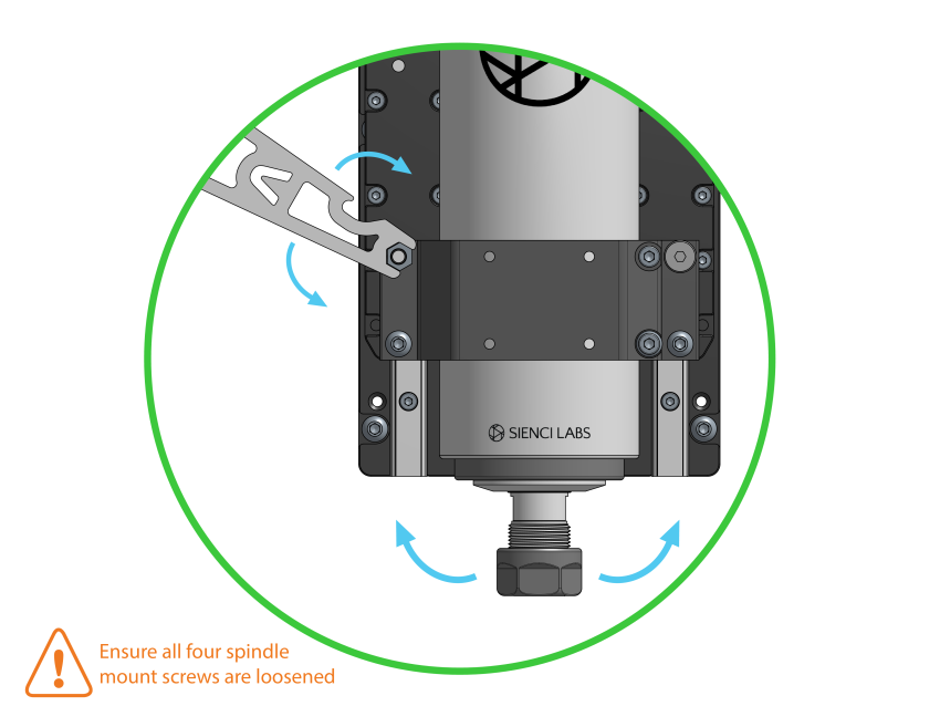
To allow for adjustment of this, simply swap the left shoulder screw, to use the ‘Eccentric Bushing’, and extra M6-25mm button head cap screws inside this hole instead. Slightly loosen all four screws securing the spindle mount to allow the mount to pivot.
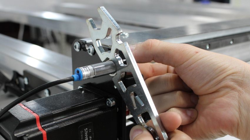
To finely adjust the tram of the spindle, use the small end of the included AltMill wrench to carefully rotate the hex of the eccentric bushing as shown below. Depending on where the eccentric bushing is angled, turning the wrench will cause the spindle to move some small amount.
For very fine adjustment, it may sometimes be necessary to gently knock the top of the spindle with a small rubber mallet, or the back of a screwdriver handle. Once finished, simply tighten all four screws.