
Preparing Your Design
Material Size and Type
Before you can start your design, you must know the size and thickness of your material. This is necessary for generating successful toolpaths. Your design should also take into account the material type. Machining different materials will result in different feeds and speeds that will be determined in the CAM software.

File Creation
Design, CAM, and Machine Interface software are all used to create the final file for your project. Detailed information about software and the CNC tool chain can be found here. https://resources.sienci.com/view/lmk2-software-explained/. In the following explanation, Carbide Create and gSender will be used for the Design/CAM and Machine Interface software examples.
Design Software
A design is needed to create the toolpath. You can use a pre-made design or create one yourself. CAD software like Fusion 360 & SketchUp are useful for creating 3D files with complex shapes. Graphic programs like Adobe Illustrator or Inkscape are perfect to create files for signs and simple 2.5D carvings.
CAM Software
We’ll now switch to the CAM software. Remember those material dimensions you took earlier, you’ll now input them into your new file. Choose the X and Y location of the zero point in the software. The Z location will either be at the top or at the bottom of the material. The starting or zero point is where the machine will reference from. In the example below, you can see the zero starts at the same location in the software and on the material.
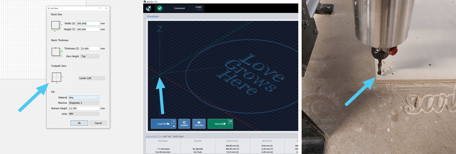
Import your design file into the CAM software. You’ll now choose the CNC bit to create the toolpath. The shape and type of bit will determine the final look of your piece.
Choosing your CNC Tool
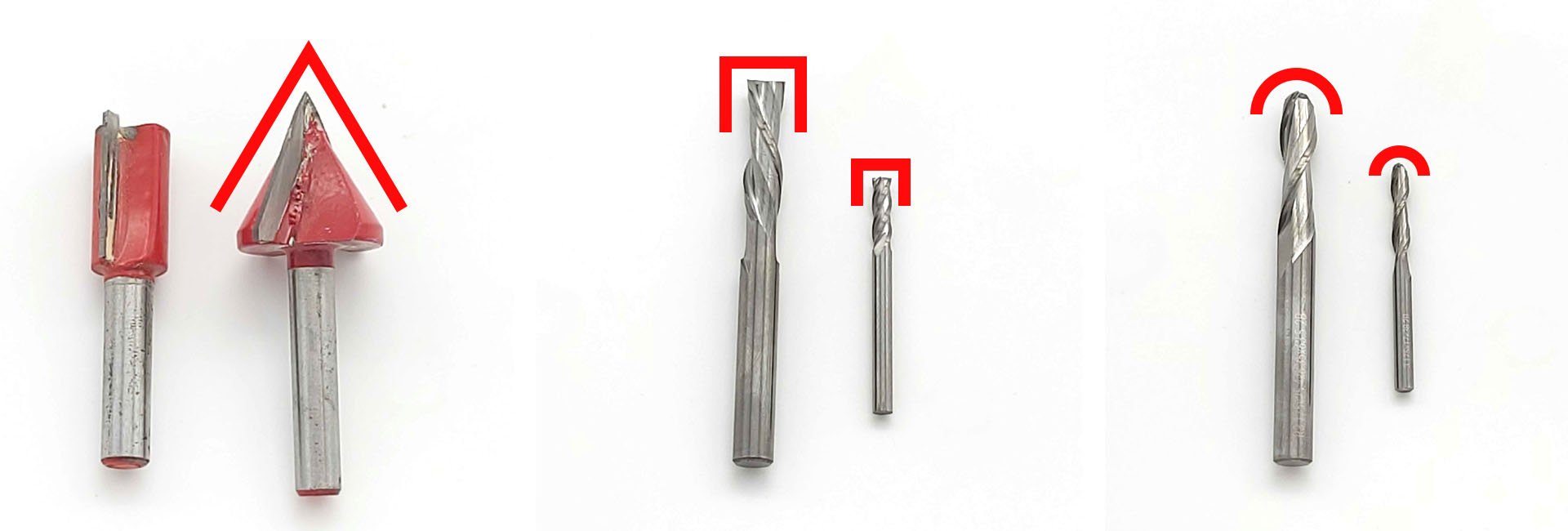
CNC bits come in a variety of shapes and sizes. You don’t need a specialty bit to get started. Common router bits are a great way to get your feet wet with machining without spending a lot of money. Common bit shapes are: V-bits; great for signs and lettering. Square End mills; used for carving pockets with flat surfaces. Ball nose and tapered bits; used for relief and detail carvings.
Creating Toolpaths
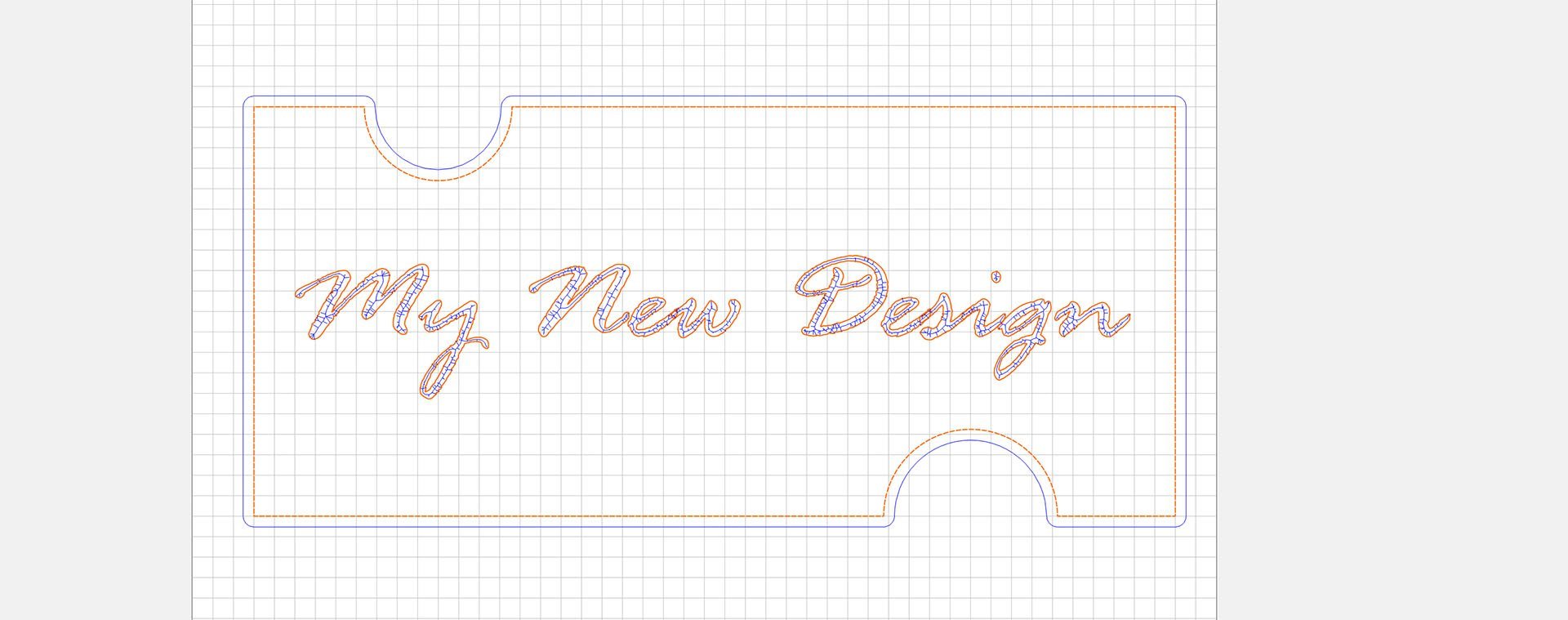
Select the vector lines you want to machine then select the CNC bit. Change any parameters such as feed and speeds for your machine and material. Information on feeds and speeds can be found here. https://resources.sienci.com/view/lmk2-feeds-and-speeds/ The CAM software will calculate the toolpath. In the example below, the design is in orange, and the toolpaths are blue. Once you are happy with the design, export the g-code.
Exporting the File
With the design finalized, it’s time to export the toolpaths. Make sure you’ve selected the correct post-processor for your machine. The LongMill uses a grbl post-processor. Save or export your toolpath to a location on your computer.
Preparing your Material
Material Clamping
Clamping material to the work surface is necessary for a successful part. Clamping methods are determined by the design and material you are using. Below are common examples of clamping methods. Small items could be held in a vice with some care. Clamps can be made out of metal, plastic, or wood.
Top Clamping
Hold down clamps hold the material tightly to the work surface. Top clamping is perfect when using upcut bits. Careful consideration must be given to the placement of the clamps in order to prevent the bit from cutting into them.
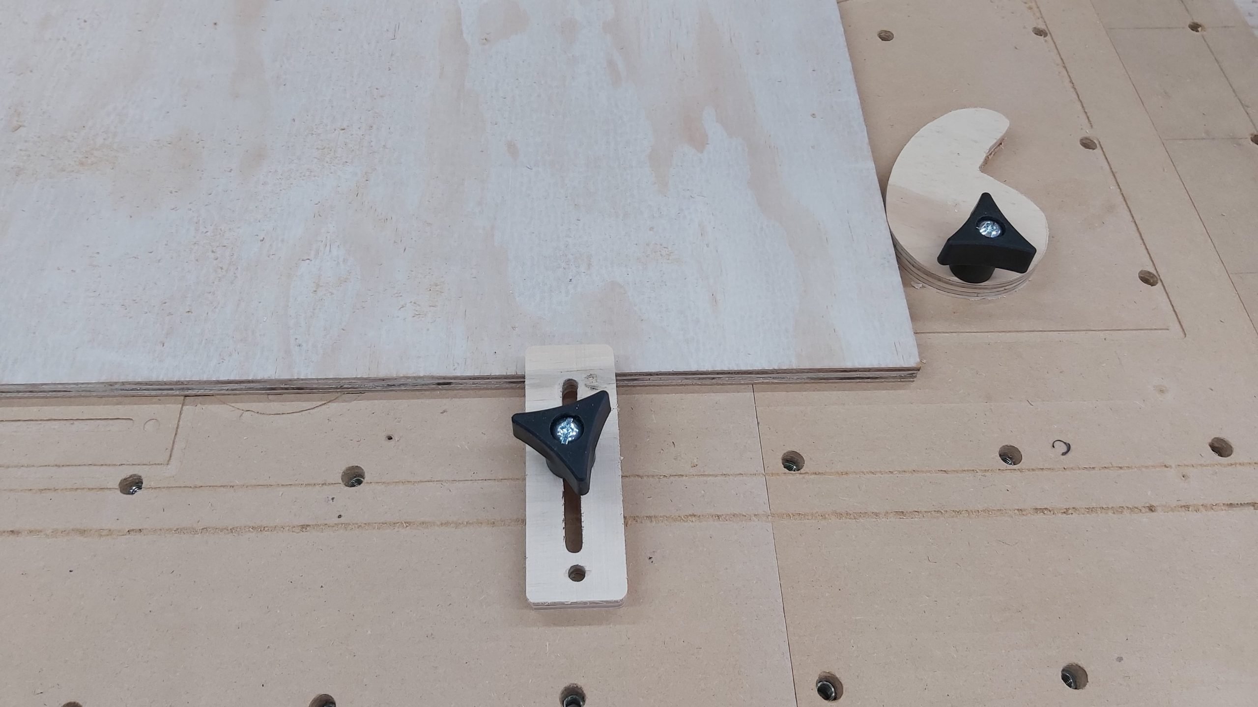
Side clamping
Holding your workpiece with pressure from the sides is useful for flattening the top of a workpiece or doing 3d reliefs where the design extends to the edges. Eccentric clamps or angled blocks pressed against material work well.
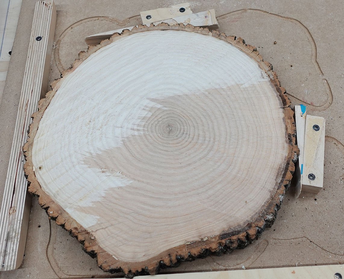
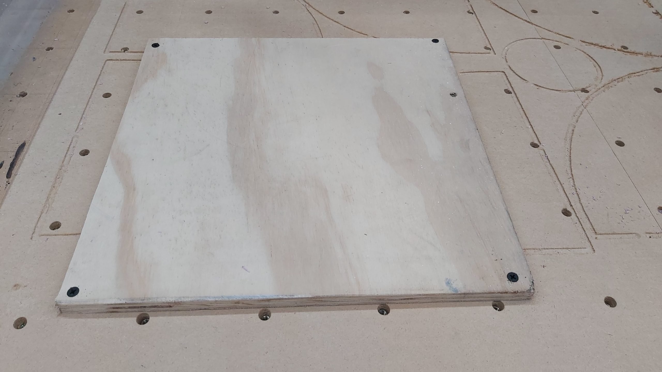
Screws
Screwing through your material and into the work surface is an excellent holding method. Extra care needs to be taken that you don’t run the bit through the metal screws.
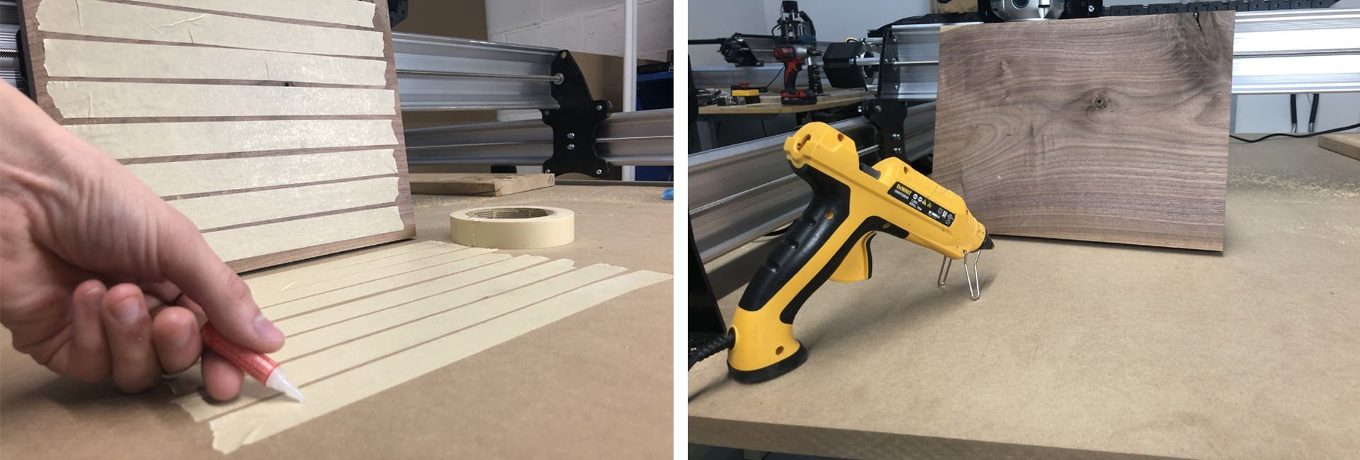
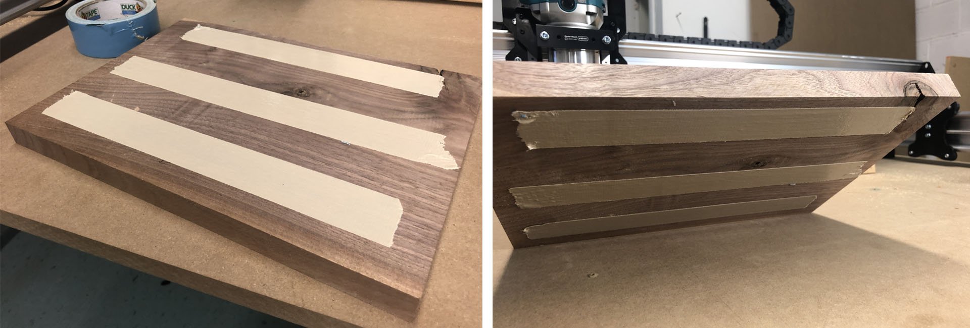
Tape and Glue
Tape is applied to the back of the workpiece and to the top of the work surface. Apply fast-acting glue to the work surface and place the workpiece on top with pressure until set. Once finished, remove the tape. Hot gluing your material to the table is also an effective way to hold the piece down when doing light machining.
Double sided carpet tape is very easy to use. It’s applied to the work surface, then the work piece is pressed to the table.
Installing the Cutting Tools
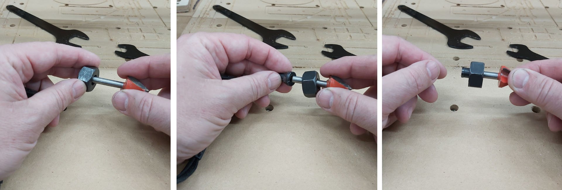
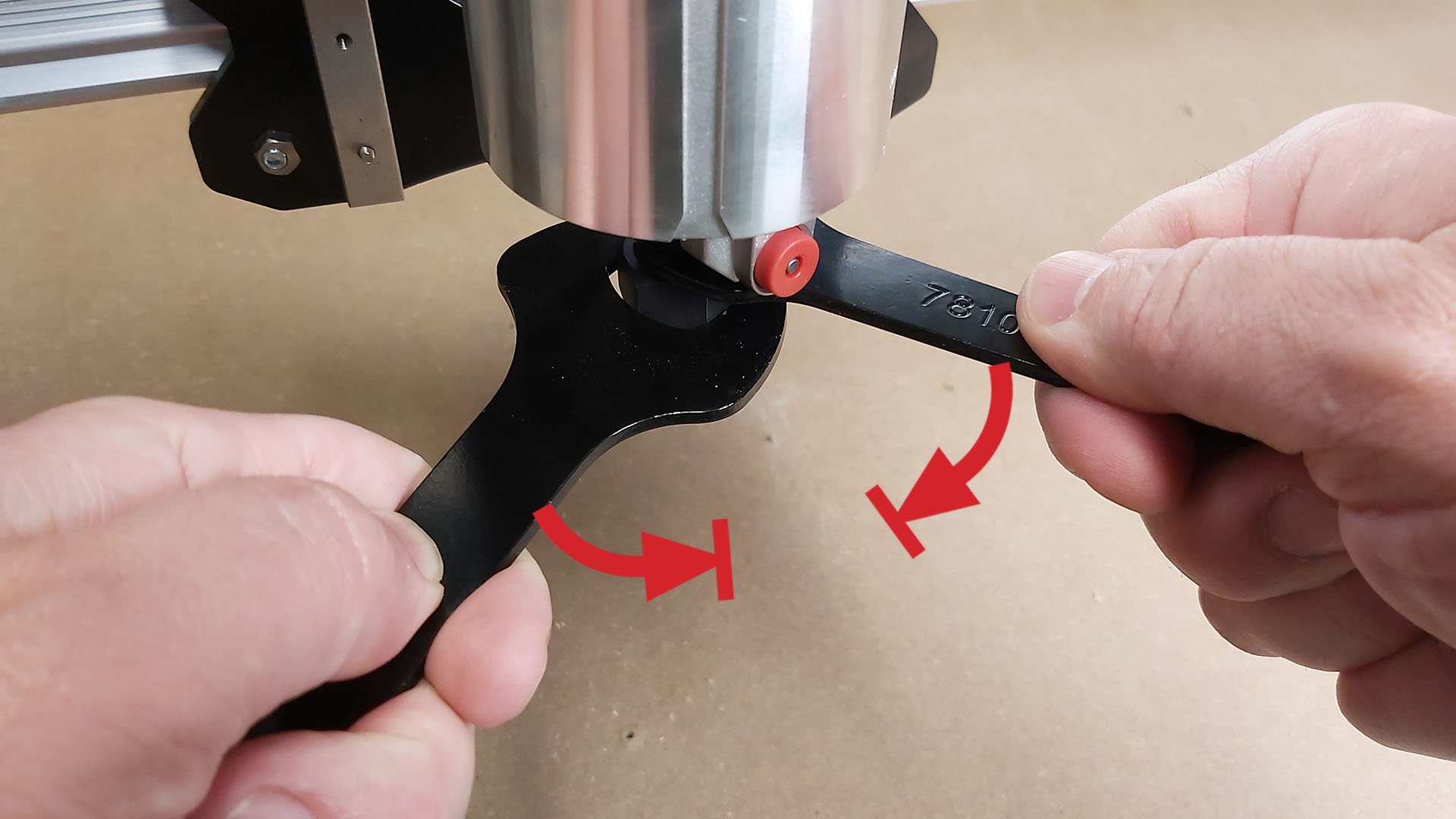
Bring the machine to the front so you have easy access to the router and collect the two wrenches that are included in the Makita box. If this is your first time using a router, look at the bottom where it has a large hex nut and notice just above this the two flats cut into the router shaft. You’ll be using the two wrenches here, one on the nut and one on the flats of the shaft, so the router can ‘clamp’ onto bits before cutting and then release them when you’re finished.
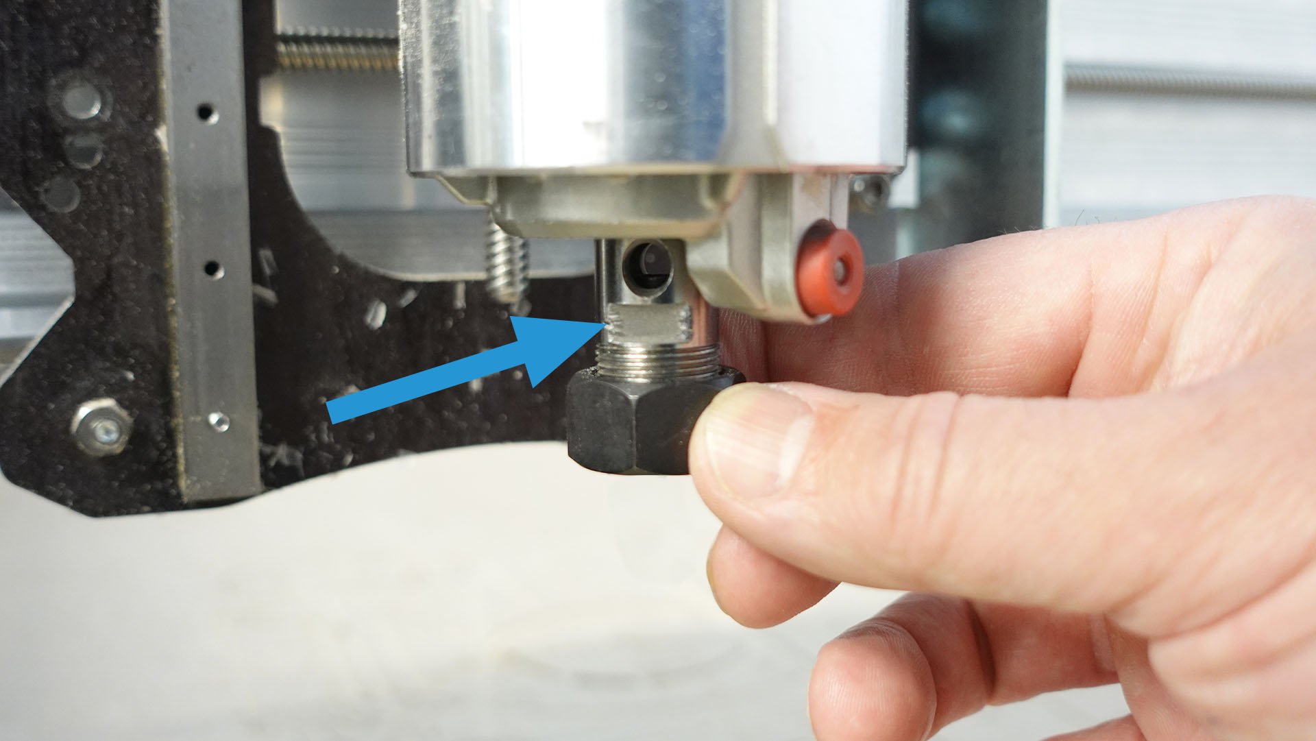
To loosen the collet nut, place the small wrench onto the router shaft on the left side. Place the large wrench on the collet nut on the right side. Squeeze the wrenches together till the collet nut is loosened.
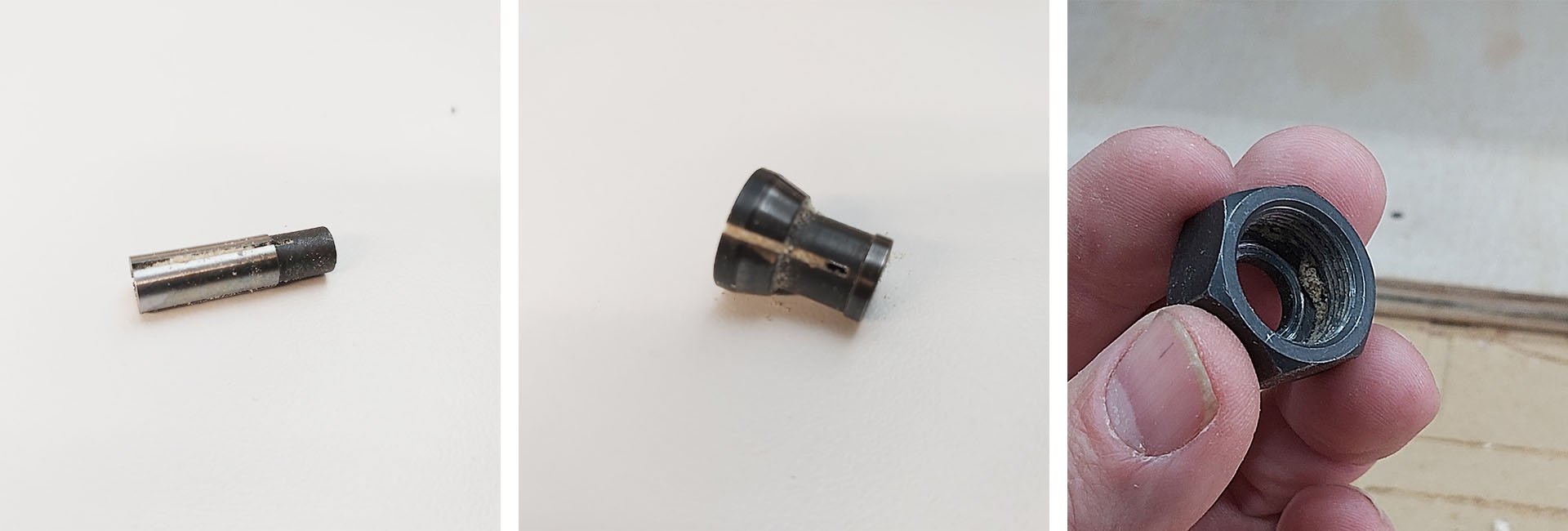
Always make sure the collet, the adapter, and the nut are free from debris before running. Dust buildup will prevent the collet from being tightened correctly and can ruin a workpiece. Dust can build in the inside corners of the nut and will prevent proper tension. Clean with a small tool or compressed air.
1/4″ diameter straight bits can be installed into the collet first then inserted through the nut before installing into the router.
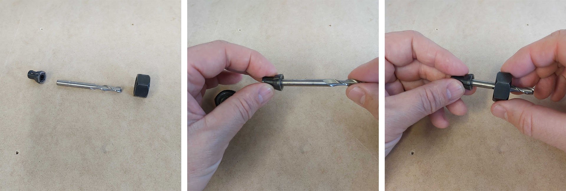
When using ⅛” bits, an adapter or ⅛” collet is necessary. Slide the ⅛” collet adapter into the standard collet, insert your bit, then place it into the collet nut and fasten to the router. The collet adapter should just peak through the bottom of the collet.
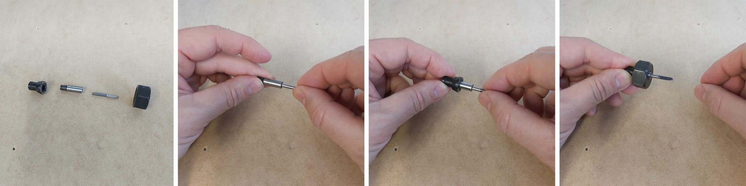
Some bits like v-bits or surfacing bits require the bit shaft to be placed through the nut first, then into the collet.
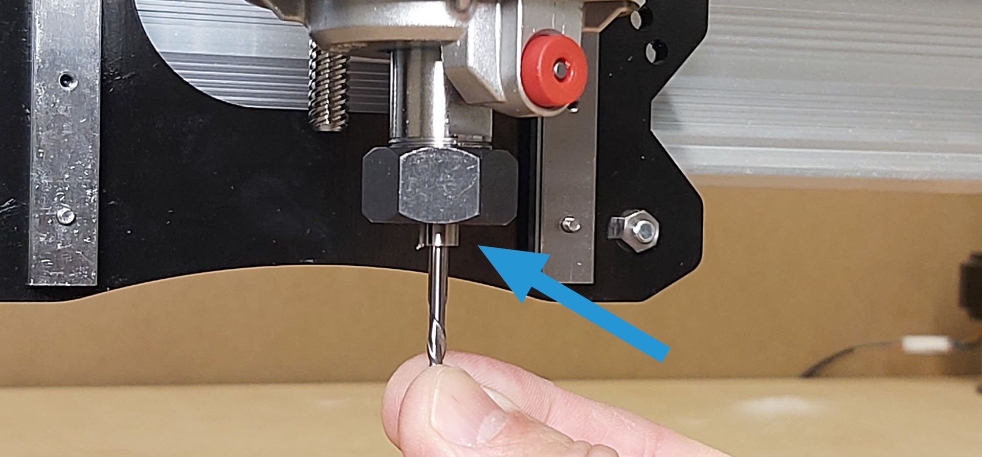
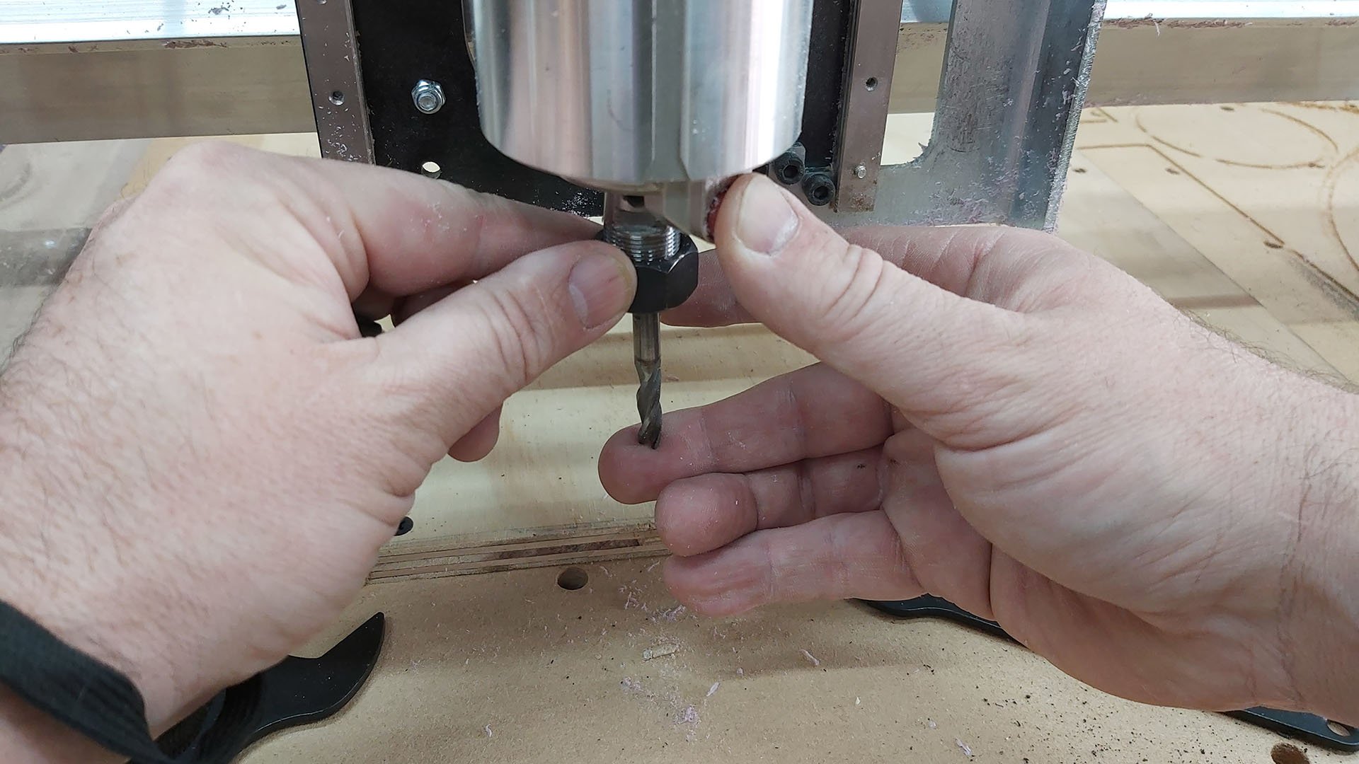
When installing the bits into the router, always tighten using the wrenches. The router can be damaged using the button and wrench when tightening. Loose bits can be tricky. Hold the bit in place with one finger. Press the red button with your thumb to lock the shaft in place. With the other hand finger tighten the collet nut till the bit can be held on its own. Use both wrenches to tighten firmly. IDC Woodcraft has a great video outlining these sorts of things to watch out for.
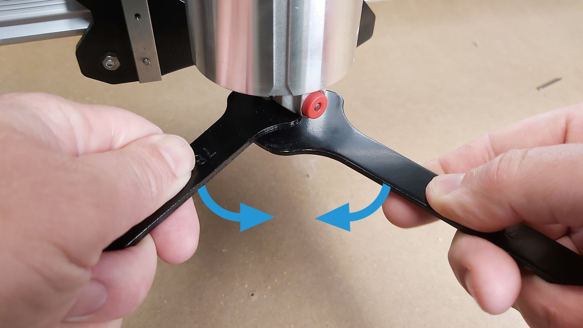
To tighten the collet nut, the small wrench is on the right side of the router shaft. Place the large wrench on the collet nut on the left side. Squeeze together until the nut is tight, do not over tighten.
Zeroing Your CNC
It’s important to have the same start location on your workpiece as in your design file. Zeroing the machine can be accomplished in two ways, manually or automatically. Open machine interface software such as gSender or UGS and connect to your machine.
Manual Zeroing
Manually jog your machine to the starting location. Zero the X and Y locations. Below are two examples of typical start locations; bottom left corner or centre of the material.
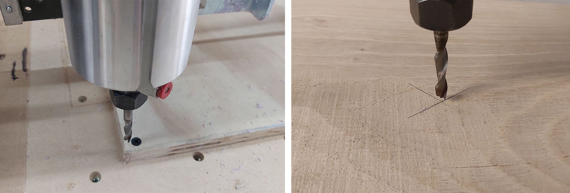
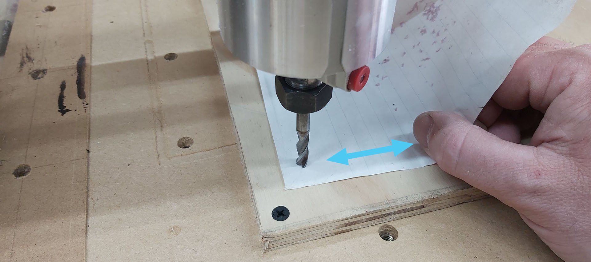
Lower the bit to the material by jogging the Z-axis down. When you are just above the surface, change to precise jogging. Place a piece of paper under the bit. Move the paper back and forth and at the same time, lower the bit. When there is resistance sliding the paper, the bit is at the correct position. Zero the Z location in the software. Raise the bit, go to your x and y starting positions and you’re ready to begin.
Automatic Zeroing
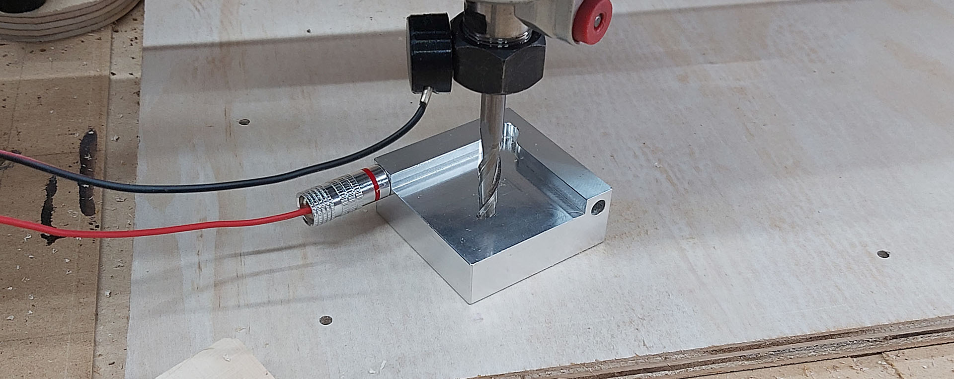
Automatic zeroing or probing works by touching a conductive plate with your cnc bit to find the coordinates on the workpiece. The touch plate can find a single axis per probe or multiple axes. Our auto-touch plate allows you to use v-bits for automatic probing. https://resources.sienci.com/view/lmk2-touch-plate/#autozero-touch-plate
To find the XYZ axes, place the touch plate on a corner of the material and perform the XYZ probe operation. The router will automatically move through all three axes. It will touch on the top and two sides to accurately find the corner. Detailed information can be found here https://resources.sienci.com/view/gs-using-gsender/#probing
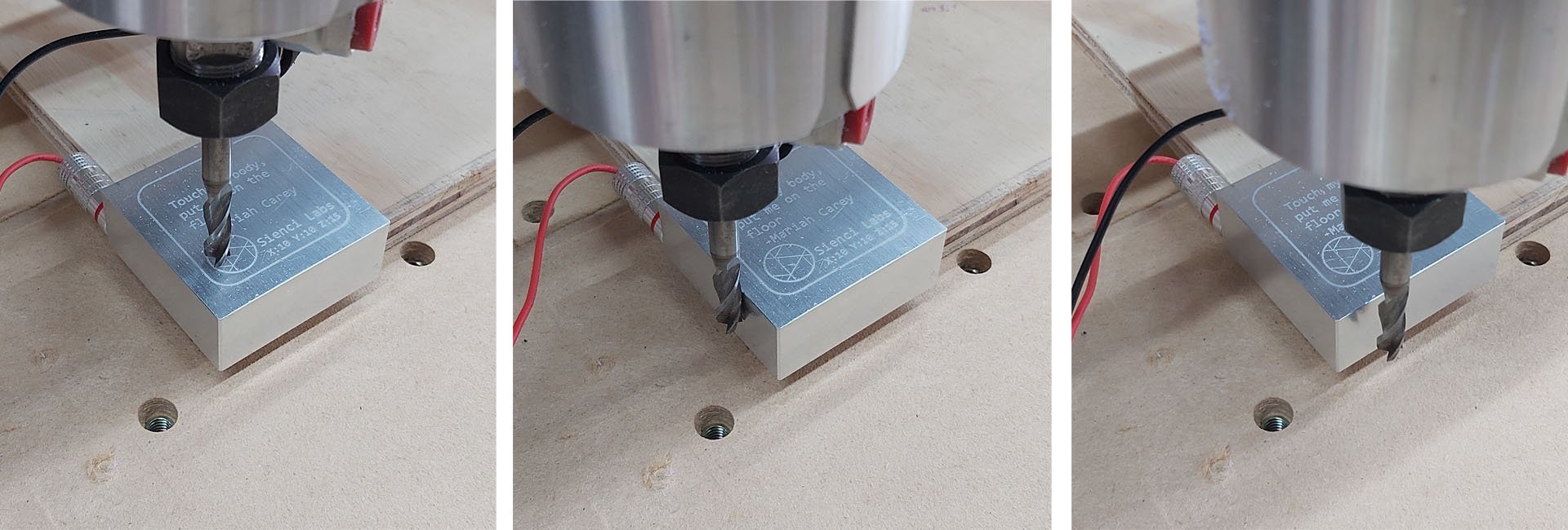
When you only want to do a z-height probe, useful for multi-bit tool changes, flip the touch plate upside down. Use the Z probe function This will find the top surface of the material.
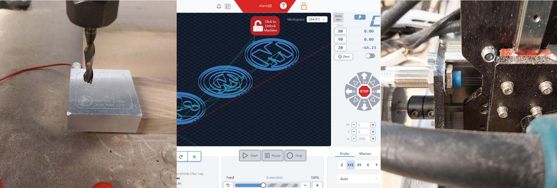
If you have limit switches installed, you might encounter an Alarm 2 message. Your material is too close to the sensors for the machine to travel safely. Move your material away from the sensors and begin your probe operation.
Pre-Flight Check-List
Sometimes it’s useful to have a list of operations next to your machine. We’ve compiled a list to confirm everything is ready to go before hitting Start.
- Ensure material is square with spoil board/machine
- Tighten clamps
- Correct bit installed
- Collet tightened
- Correct router speed
- Correct g-code loaded
- Home machine – if using limit switches
- Zero X and Y axes
- Zero Z axis
- Check toolpath won’t hit clamps
- Turn on router
- Turn on dust collection
- Start job
Overriding the Machine for Fine Tuning
Sometimes when you start the job, you’ll need to make adjustments to the machine for proper chip load.
Feed Rate Using gSender
When a job has been started, gSender will show a feed adjustment control panel beside the machining time. Clicking on the plus or minus button will adjust the feed rate 10% faster and slower. You can also adjust the slider to the right to speed up and to the left to slow down. The speed is always reflected in the blue text above the slider. Hitting the circle arrow on the left, will reset the feed to 100%.

It’s important to remember, however, that while you may want to modify the cutting feed rate for some cutting operations, the machine will continue using this feed rate override for subsequent cutting operations. For example, if you’ve overridden the feed rate by 200% while cutting the outline of your project at very shallow depths, you’ll want to reset the feed rate to its original speed before it next moves on to cutting out a pocket at a much deeper depth.
Spindle Speed
The RPM on the router can be changed on the fly by rotating the dial indicator to a faster or slower speed. Below are approximate RPMs for each number on the dial.
| Dial # | 1 | 2 | 3 | 4 | 5 | 6 |
| RPM | 10,000 | 12,000 | 17,000 | 22,000 | 27,000 | 30,000 |
Tool Changing
As you begin tackling more complex CNC projects, you’ll start to notice that running multi-tool jobs becomes a necessity. Using multiple bits on the same workpiece can save time or achieve greater detail and give you the carving flexibility you need; whether it’s a v-bit for engraving and an end mill for profiling, or an end mill for roughing and a tapered bit for finishing.
Method 1: Separate Files
This is the easiest and most straight forward approach to tool changing. Many CAM programs allow for each toolpath to be exported as separate files. By creating separate g-code files for each cutting tool you’ll be using, you can just:
- Start with your first tool and first file
- Wait for the file to complete then jog your router off to the side
- Change the cutting tool out for the second one
- Use a touch plate or tool length sensor to measure the new zero point (off your wasteboard or material, depending on how you set up the job)
- Reposition and run the second file
- Repeat this process until completion
Just be sure to give each file a clear naming scheme so you execute them in the right order and with the right tool. For example, your first file could be called “cat_1_v-bit”, then your second “cat_2_endmill”, and your third “cat_3_tapered”. You can also specify the tool size or angle, any other prompts that ensure you run the order of files successfully with their corresponding bits.
Method 2: Manual Editing
This method will also work for g-code sending programs that do not have tool changing functionality, the difference with this one is that all the toolpaths will be in one file. The instructions below are written in millimetre values, however you can replace the values to be in inches as long as the g-code was generated using inches.
This is a tool change method inspired by the work of Stuart McRae (a LongMill customer).
Setup
- Generate your g-code to the file format .nc or .gcode.
- Zero your machine in the X, Y, and Z on the mounted stock material.
- Open up the g-code using NC Viewer and check the first few lines for the callout of the correct units (G20 for inches, G21 for mm) and for G90, absolute coordinates.
- Go line by line to find where the tool changes should occur, by looking at the toolpath visualization on NC Viewer. Use your mouse or keyboard to move to each line, and you should see an end mill following the coordinates called out in the g-code.
-
Add the following g-code for each tool change.
G-code Explanation Z20.00 Raises the bit to 20mm above your zero. X?.??Y?.?? Moves bit to a defined XY position. This is the location of your tool change. CHANGE THIS to a position in which the stock material hasn’t been cut, and is accessible. M0; Pauses job. This is when you turn off the router, change your bit and lower your router manually via Z-axis pulley to zero the bit with a piece of paper. Once you are done you will turn on the router and press PLAY on the g-code sender program. G92Z0.125 Sets the current Z position as 0.125mm (paper thickness) above your zero. So it now knows where the Z-axis zero is. G0Z25.00 Raises your bit 25mm above your zero. - Save the g-code you just edited as a new file on your computer.
- Load the file into your g-code sender program.
- The machine will run through the first toolpath, cutting into the material, then will lift up and move to the bit changing position you defined. It will stop moving, in a HOLD state, until you press PLAY. Complete the tool change and zero the machine manually – note that the surface will be marked by the bit once you turn your router back on.
- Repeat Step 8 for each tool change.
Below are some examples of how to input the tool changing g-code, which are bolded.
EXAMPLE 1: Carbide Create
G90
G21
(Toolpath 3)
M05
M0 ;T102
M03S18000
G0X12.00Y10.41Z5.00
G1Z-1.00F457.2
X36.00F1524.0
Z5.00
(Toolpath 4)
Z20.00
X5.00Y20.00
M0 ;T201 // this line was already in the g-code
G92Z0.125
G0Z25.00
S18000
G0X12.26Y22.84
G1Z-1.00F381.0
X36.26F2286.0
Z5.00
M05
M02
EXAMPLE 2: CAMLab
G21
G90
G0 X7.2948 Y-8.1954 Z2.0
G1 Z-0.6522 F2000
G1 X-16.3552
G1 Y-8.2454
G1 X7.2948
G1 Y-8.1954
G0 Z2.0
G0 Y8.6204
G1 Z-0.6522
G1 Y8.6704
G1 X-16.3552
G1 Y8.6204
G1 X7.2948
G0 Z2.0
Z20.00
X5.00Y20.00
M0;
G92Z0.125
G0Z25.00
…
Method 3: gSender Tool Change
The g-code for tool changing is an M6 command, in which the program will pause until the user tells it to continue, usually through a ‘Resume’ and/or ‘Confirm Tool Change’ button on the machine interface program. In CAM programs, this M6 will be inserted in your g-code if there are toolpaths using different bits, thus requiring tool changes. On gSender, you can program what happens when there is M6 in your g-code, therefore allowing you to easily change your bits with pre-programmed actions. Full instructions can be found here.
Post-Processing Work Pieces
Now that you’ve got your piece machined out, finish the design with a nice smooth finish or an amazing paint job.
Sanding
Depending on your project, getting into the crevices of your design can be difficult. Small scrapers are handy to remove fuzzy bits. Cone Sanders are useful for larger designs. What if you carved a 3D relief? Sanding mops in different grits work great here. They can get into the details without removing too much material and ruining the design.
Painting/Staining
There are a few ways to add colour to your work piece. Wood stains help enhance the grain of the wood and should be finished with a good sealer, Multi-Colour painting can also really make a sign pop in which case it’s recommended to use a masking film.
Sealing/Finishing
To protect the surface and details of your project, a finishing product such as wax, lacquer, varnish, or epoxy can be used. On projects such as a cutting board or serving tray that may encounter water, or be used in direct contact with food, the appropriate food-safe finish should be used to seal your project.