
Parts List
- 1x E-Stop Assembly
- 1x SLB-Ext Controller
- 1x E-Stop Mounting Plate (if Spindle Kit is not used)
- 1x E-stop Cable
- 1x Power Supply
- M5-10mm Socket Head Cap Screws
- M5-16mm Socket Head Cap Screws
- M5 Nylock Nuts
- Zipties
Controller and E-stop Installation
Open the SLB-Ext controller box and take out the SLB-Ext controller and the E-stop button unit.
Unboxing the Super Long Board – EXT
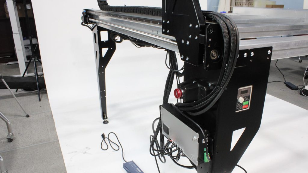
Use two (2) M5-16mm socket head cap screws to secure the E-Stop button unit, through the front left table leg into the previously-installed VFD mounting bracket behind it. Note: this is only applicable if you have the Sienci Labs Spindle Kit.
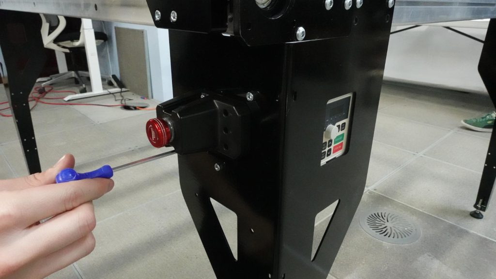
Fastening E-stop through front left leg into tapped holes on the VFD mounting bracket (hidden)
If you are not using the Sienci Labs Spindle Kit, an alternate plastic mounting plate will be used to mount the E-stop button. Grab two M5 nylock nuts, and two M5-16mm socket head cap screws. Press the M5 nylock nuts into the two hexagonal pockets, with the flat side facing into the plastic plate. Place this onto the rectangular cutout at the leg, from the inside, then attach the E-stop button with the two screws while holding the plate in place.
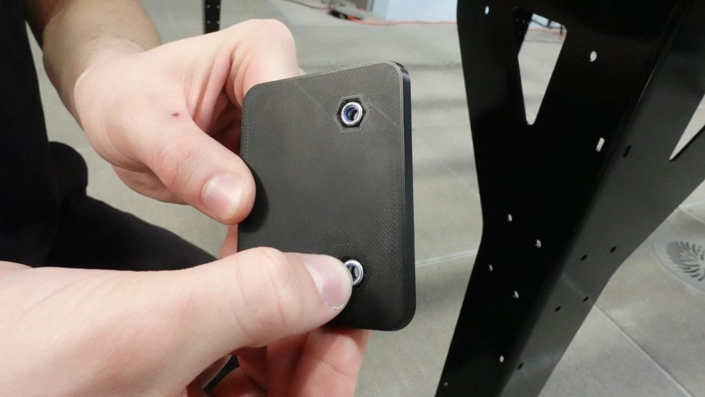
Nylock nuts pressed into plate
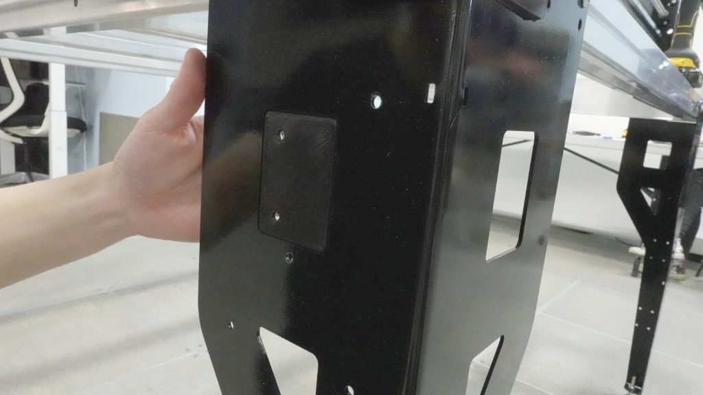
Plate positioned at rectangular cutout on leg
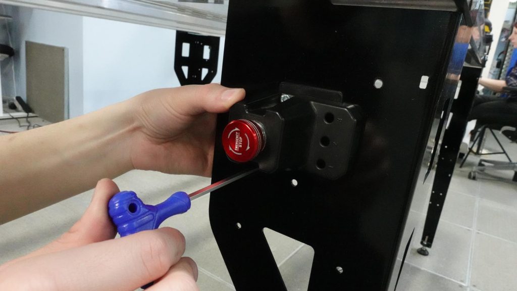
Securely fastening screws to mount E-stop
Grab the SLB-Ext controller. Depending on when you’ve ordered your AltMill, a plastic bracket with threaded holes may have been pre-installed into the rear side of your controller to easily mount the controller onto the left front leg.
If there is no bracket pre-installed, grab the included aluminum mounting bracket from the hardware bag packed with your controller. Insert this into the rear side of the controller, by tipping the bottom of the bracket into the slot as shown.
Grab two (2) M5-10mm socket head cap screws to secure this to the leg as shown.
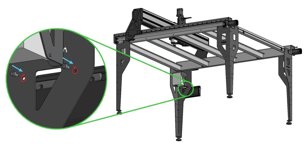
Securely fastening controller onto left front leg with socket head cap screws
Cable Connections
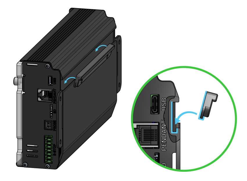
Open the controller top by loosening the thumbscrew, sliding the acrylic cover to the right, then tipping the acrylic cover out to access the motor and sensor plugs.
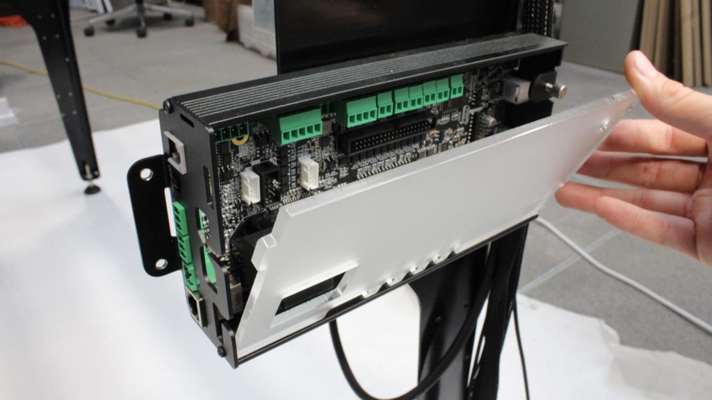
Opened controller top
Grab the bundle of cables coming out of the front of the drag chain. There are two sets of motor and inductive sensor cables (one black and one white connector per set). Locate the shorter set and insert these into the ‘Z-axis’ plug. Insert the longer set into the ‘X-axis’ plug. The 2-prong motor power connectors can be plugged into any of the four motor power plugs since all motors receive the same power.
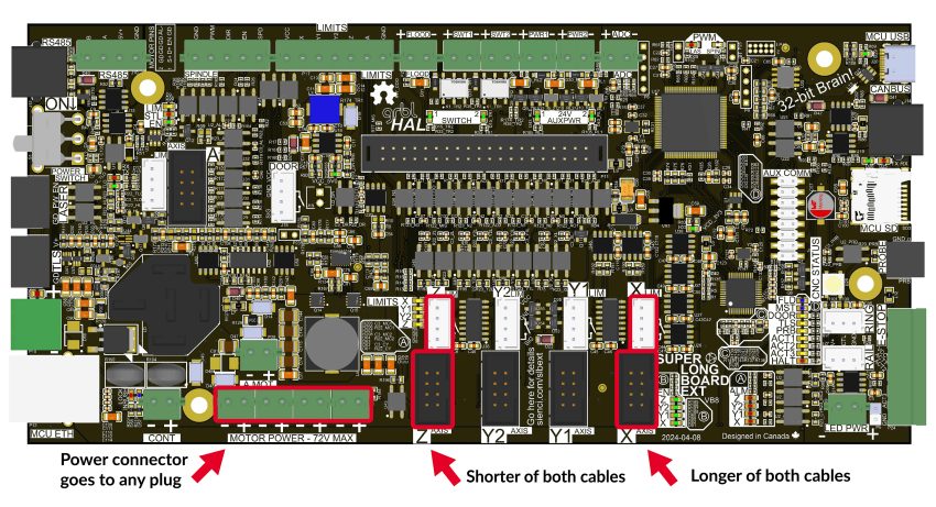
X and Z power, motor and sensor signal plugs on the controller
X and Z cables plugged into controller
Grab the bundle of cables from the rear of the machine that are used for the Y-axis motors and inductive sensors. Locate the longer of the two sets of motor and inductive sensor cables, and insert these into their respective ‘Y1’ plugs as shown. Connect the shorter of the two cables into the ‘Y2’ plugs. Make sure the cables are correctly plugged in, do not mix up the Y1 and Y2 cables or else you will encounter an alarm during operation. The 2-prong motor power connectors can be plugged into any of the four motor power plugs.
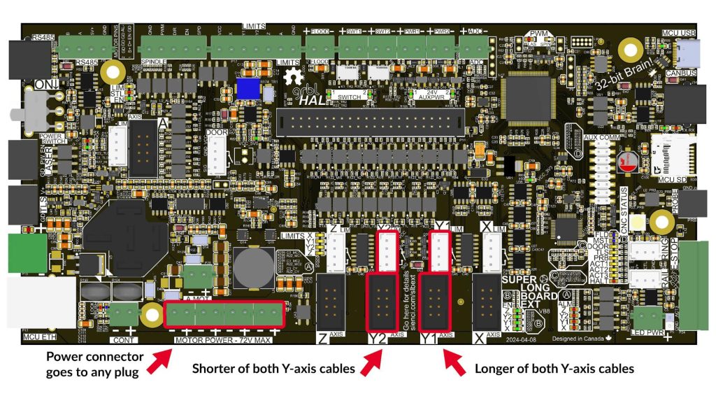
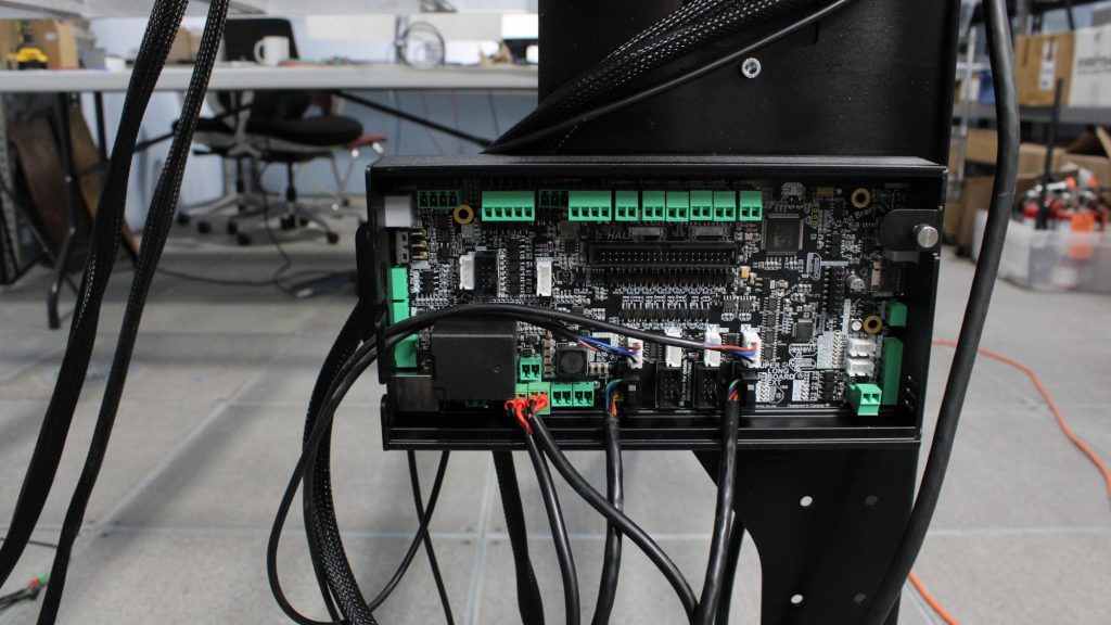
Y1 and Y2 power, motor and sensor signal plugs on the controller
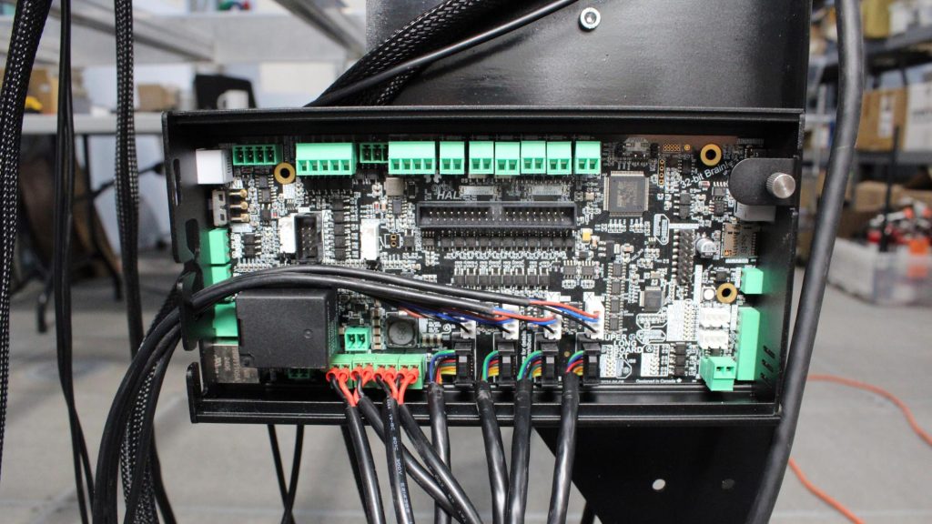
Completed controller wiring
To finish off the X, Y, Z-axis wiring, leave the motor power and signal cables dangling towards the ground, and route the four (4) inductive sensor cables (white connector) out through the cutouts on the controller case, facing the rear of the machine. Grab the acrylic cover that was previously removed, and re-install this, slotting the motor power and signal cables through the cutouts in the acrylic as shown. Twist the shoulder screw to secure it.
Reinstalling acrylic cover
Take out the E-stop button cable. Plug the green terminal connector into the controller facing the front of the machine, and the clear connector into the rear of the E-stop button unit.
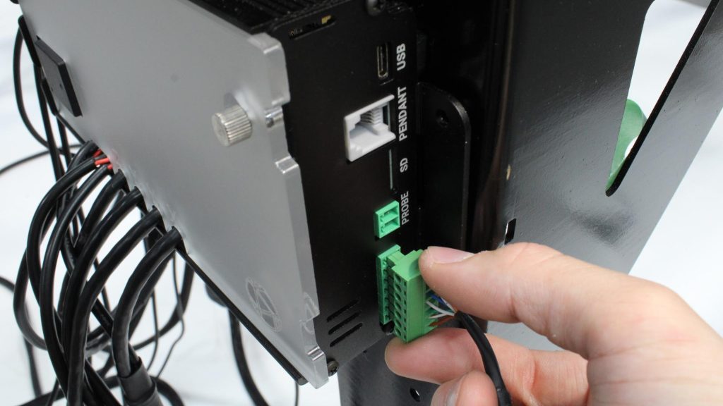
Green connector plugged into controller
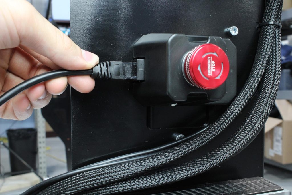
Clear connector plugged into E-stop
If you have installed the Sienci Labs Spindle Kit, grab the spindle control cable that is attached to the VFD unit, and plug this clear connector into the rear port on the controller labeled ‘RS485’. If you’re installing your own spindle, you may need to connect your own spindle control cable as explained here.
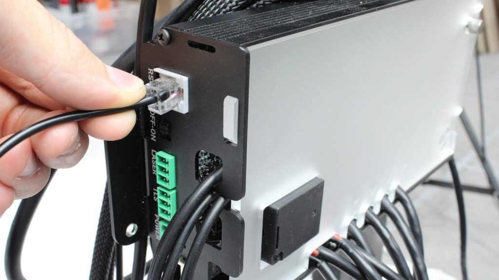
Plugging clear connector into RS485 port
Lastly, grab the 48V power supply and plug the green connector into the controller. Connect the wall plug into a 110V outlet, or use an extension cord if necessary.
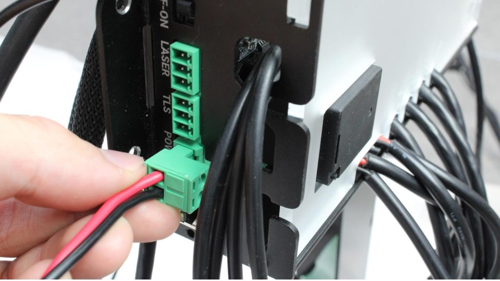
Plugging power connector into connector
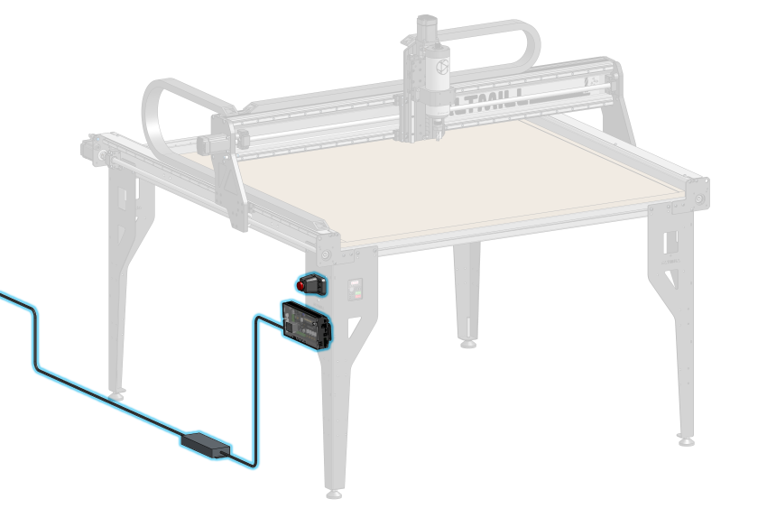
The excess cables can be managed however is easiest for your setup. Using the included larger zip ties, the bundle from the rear of the machine can be folded onto itself and tied, while the cables coming from the drag chain can be consolidated into the inside of the front left table leg as shown.
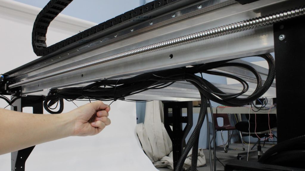
Cable bundle folded and tied underneath the machine
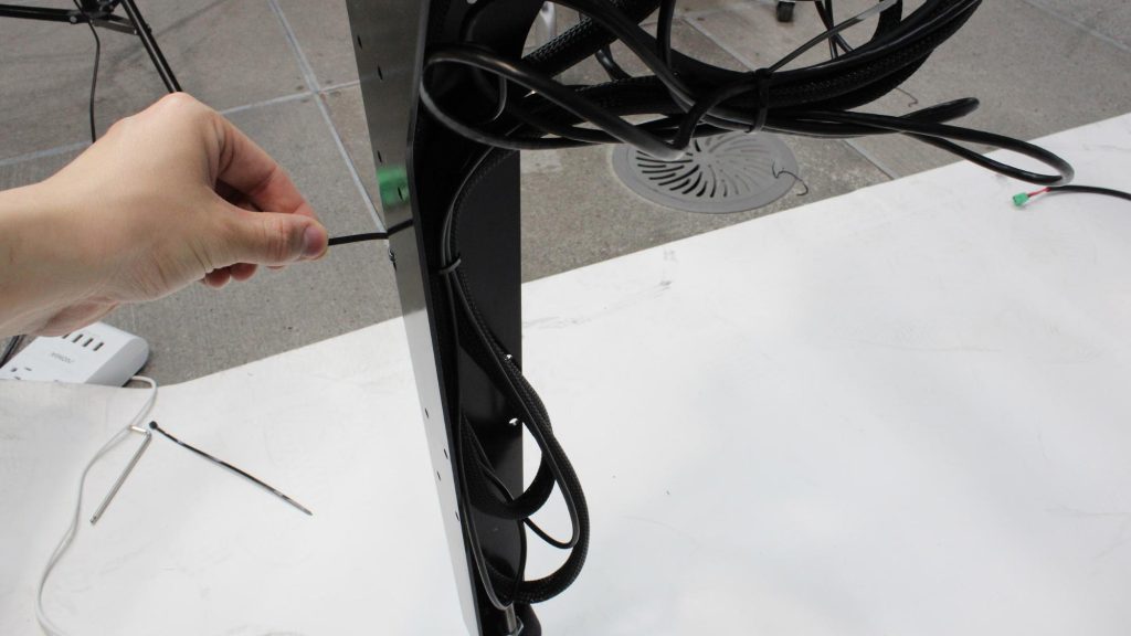
Cables from drag chain tied to inside of front left leg
Cables tied to front left leg