
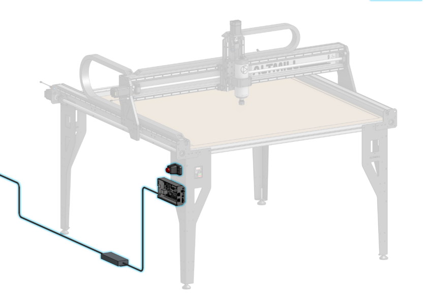
The E-stop is located in the SLB-EXT box.
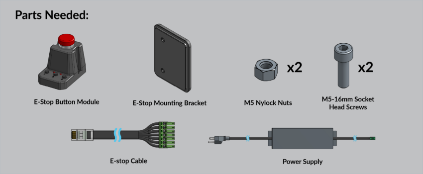
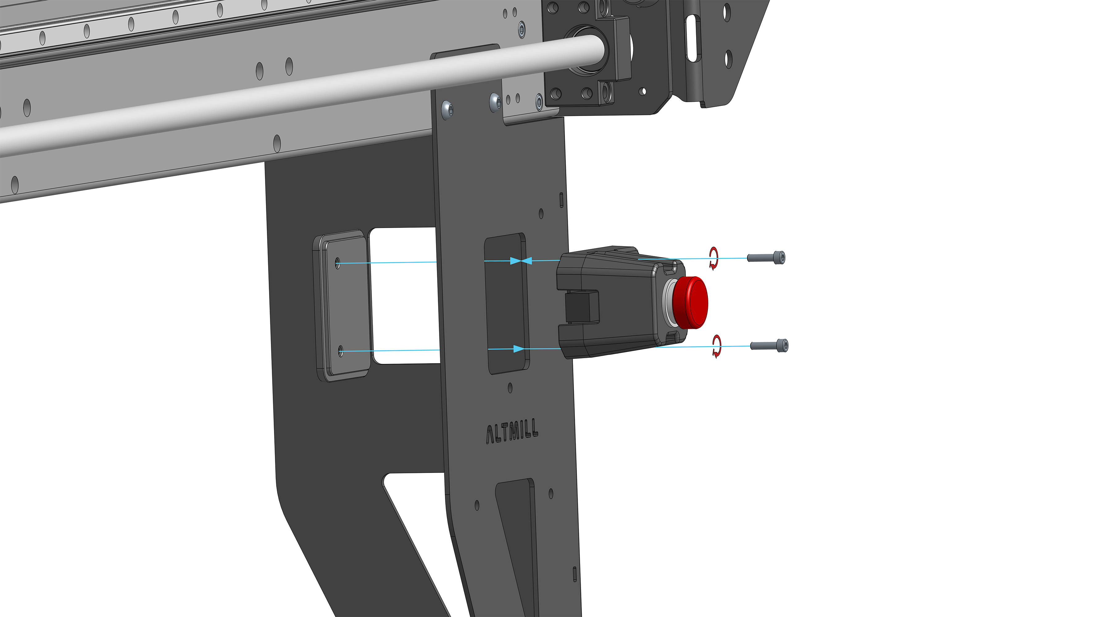
Fasten the E-stop to the VFD Mounting Bracket on the side of the left table leg, using two (2) M5-16mm socket head screws.
If you did not purchase the Spindle Kit, you will use the E-stop mounting plate provided in the SLB-EXT box to fasten the E-stop to the side of the left table leg. The E-stop Mounting plate is inserted into the left pocket from the inside of the Table Leg with the two holes oriented toward the back of the machine.
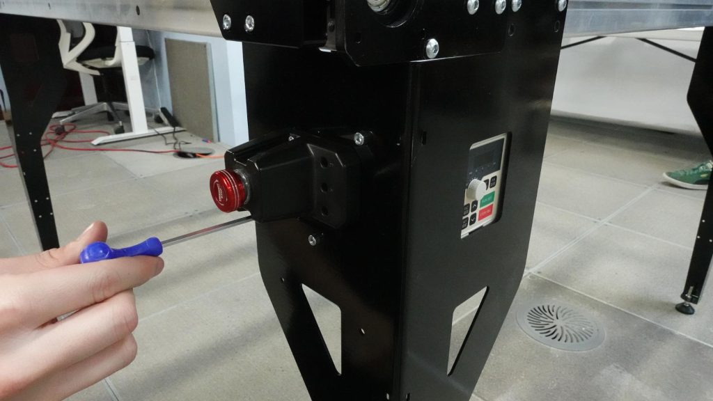
Fastening E-stop into E-stop mounting bracket
Insert M5 nylock nuts into the E-stop mounting plate. Use two M5-16mm socket head screws to fasten the E-stop to the mounting plate.
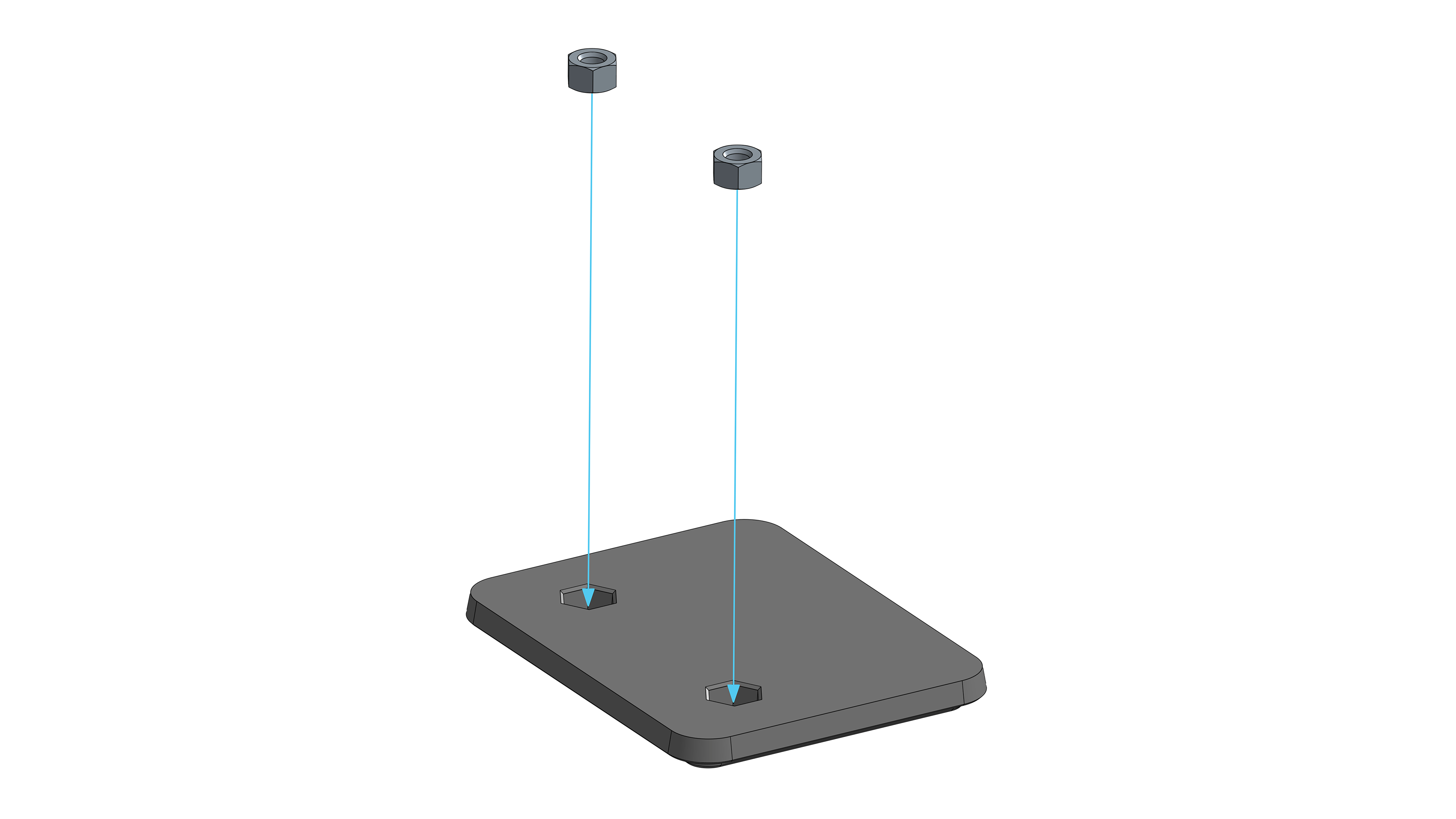
Nylock nuts into E-stop mounting plate
E-stop installed on left side table leg
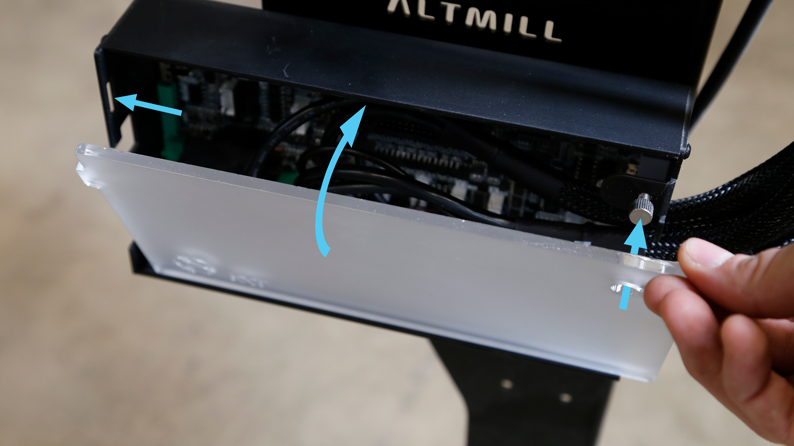
Loosen the thumb screw on the front of the SLB-EXT enclosure and remove the acrylic face plate.
Fit the Z-axis and X-axis wire harnesses into the top cut out of the enclosure on the right side. Plug the sensor and motor control connectors into their respectively named ports.
Plug the two-pronged motor power connectors into the left most power ports. The power ports all supply the same output and therefore the connectors are able to be plugged into any, however, for installation purposes we recommend you to plug into the two leftmost ports while installing X and Z.
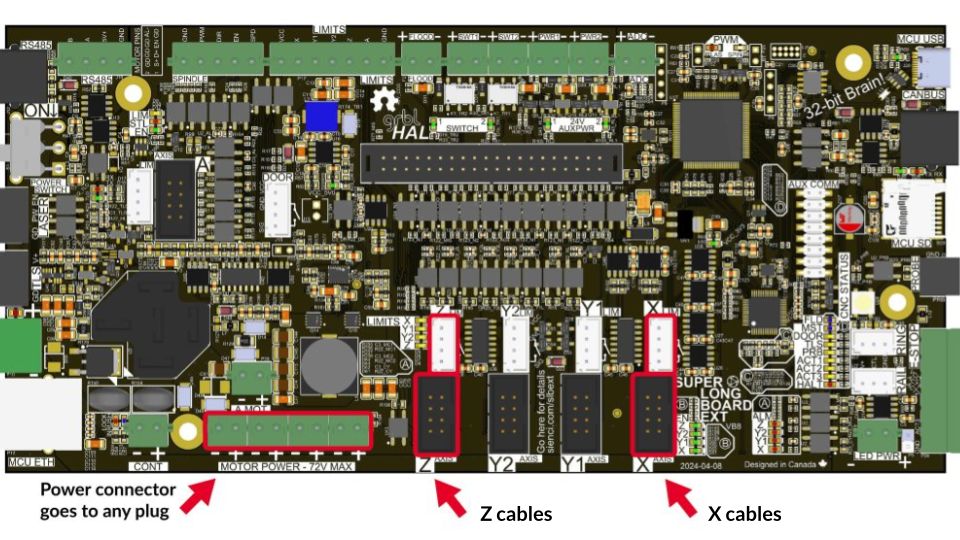
X and Z power, motor and sensor signal plugs on the controller
X and Z cables plugged into controller
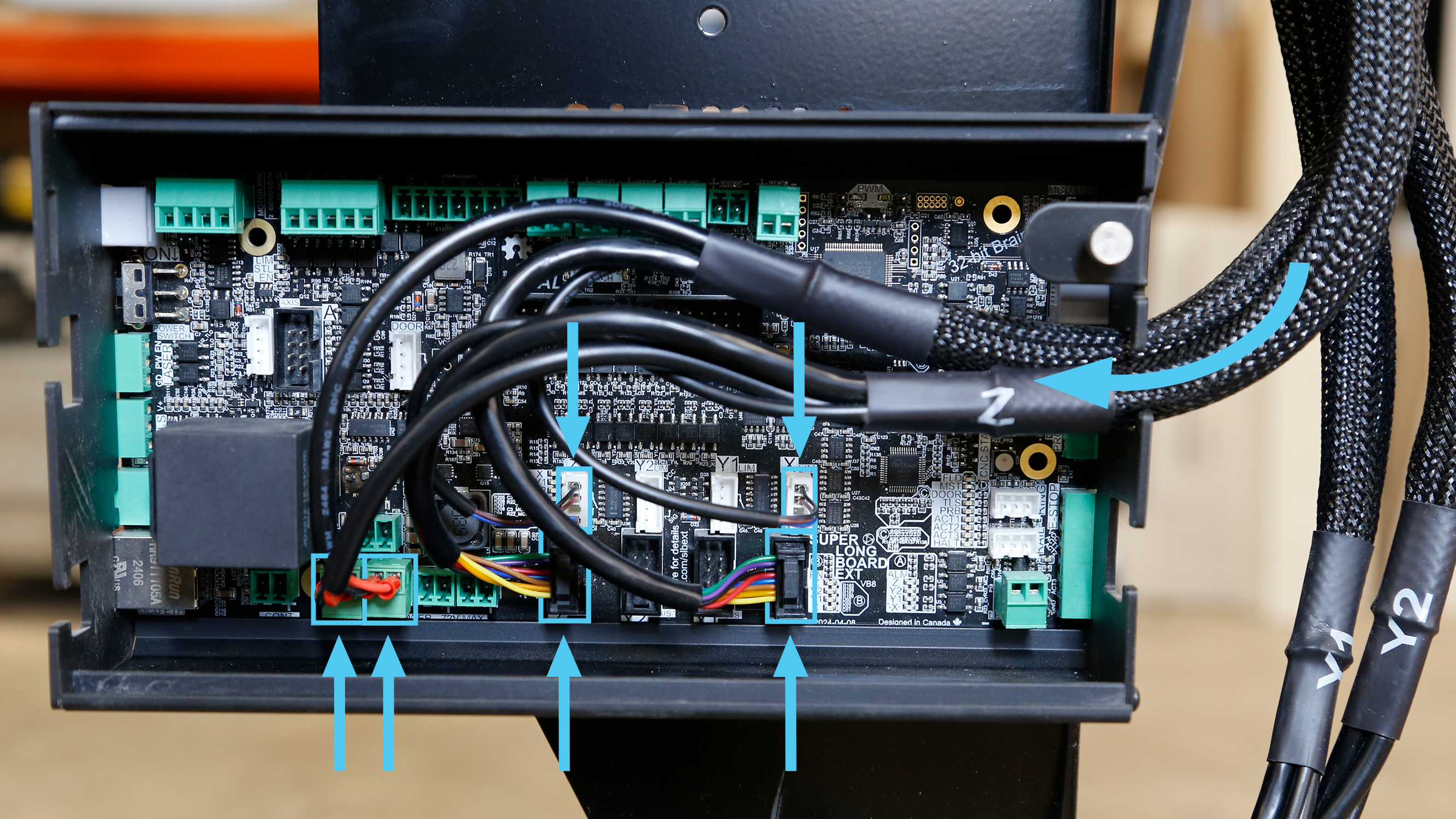
Fit the Y1-axis and Y2-axis wire harnesses into the bottom cutout of the enclosure on the right side. Plug the sensor and motor control connectors into their respectively named ports. It is important that you do not mismatch the control connector from one harness with the sensor connector of the other when plugging into one pair of Y1 or Y2 ports. If installed incorrectly you will encounter an alarm during operation.
Plug the two-pronged motor power connectors into the two rightmost power ports. The power ports all supply the same output and therefore the connectors are able to be plugged into any, however, for installation purposes we recommend you to plug into the two rightmost ports while installing Y1 and Y2 power.
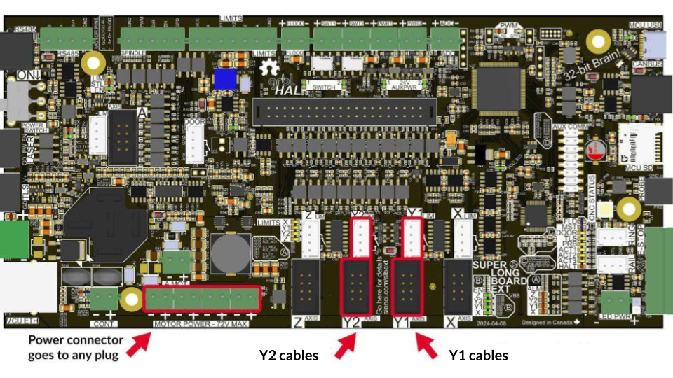
Y1 and Y2 power, motor and sensor signal plugs on the controller
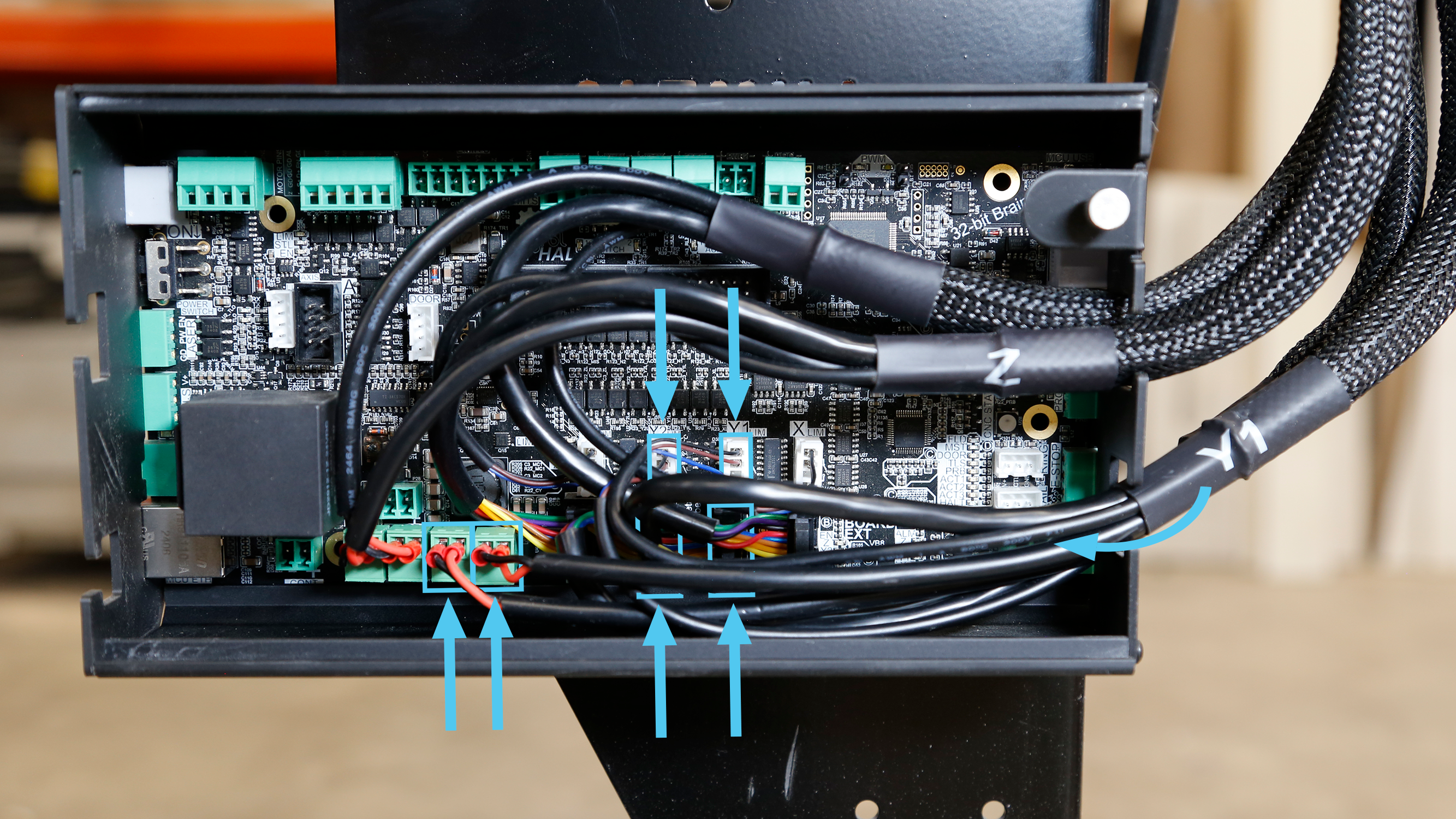
Completed controller wiring
Reinstall the acrylic face plate of the SLB-EXT onto the enclosure. Tighten the thumb screw by hand.
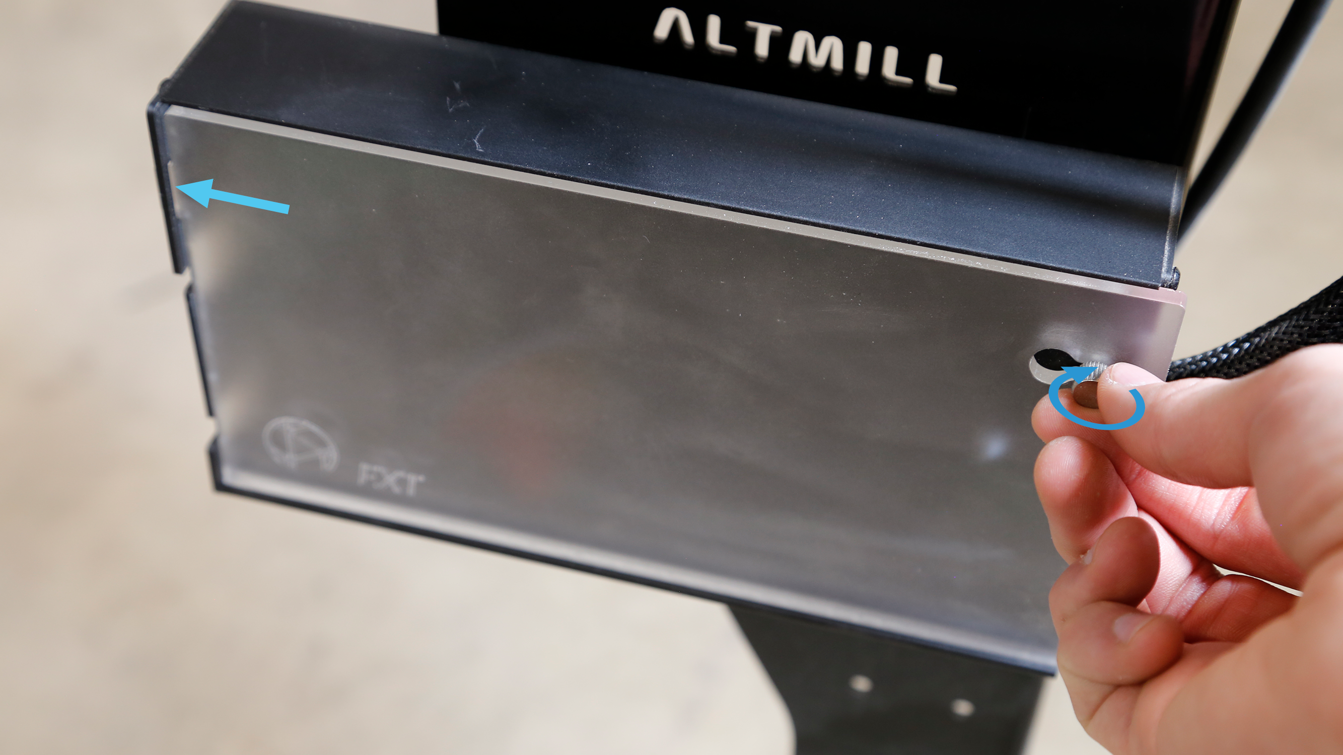
Reinstalling acrylic cover
Plug the green connector of the E-stop cable into the port labeled E-stop on the right side of the controller, and the other side of the cable into the E-stop.
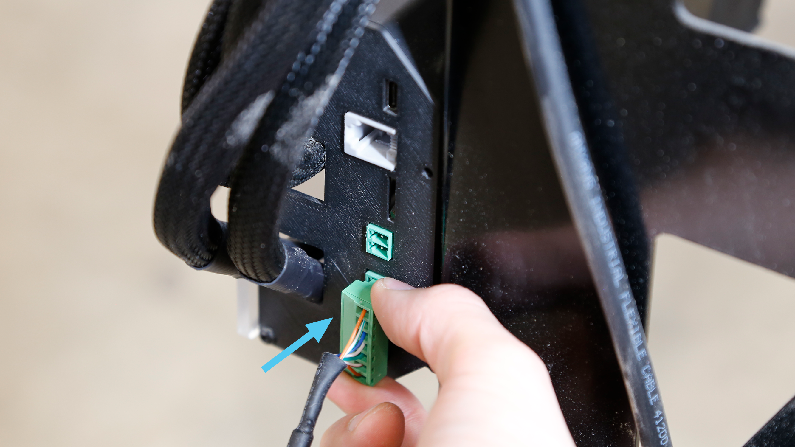
Green connector plugged into controller
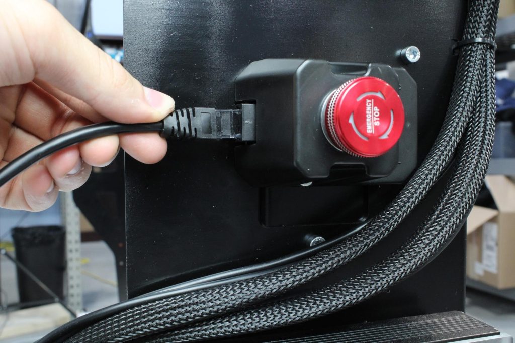
Jack connector plugged into E-stop
If you have installed the Sienci Labs Spindle Kit, plug the clear connector of the spindle control cable that is attached to the VFD unit, and plug this into the port labelled ‘RS485’ on the left side of the controller.
If you’re installing your own spindle, you may need to connect your own spindle control cable as explained here.
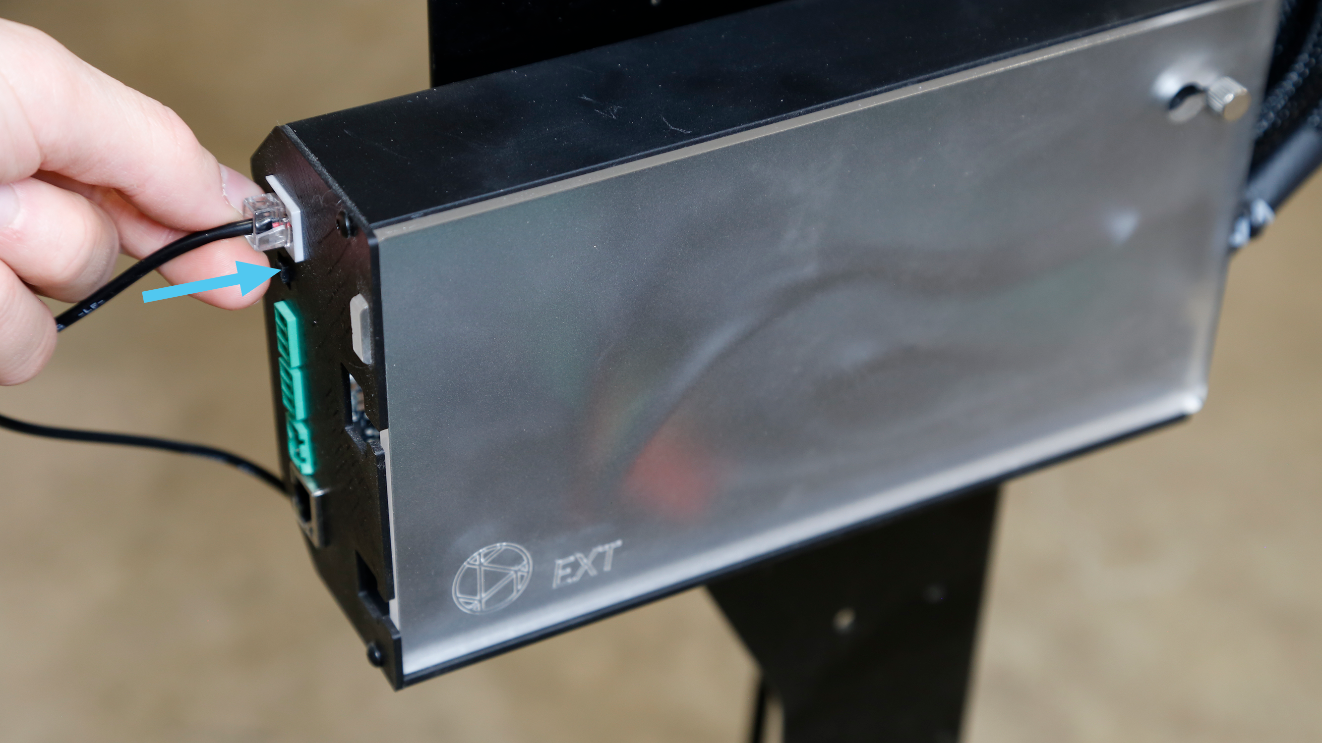 Plugging spindle control connector into RS485 port
Plug the green connector of the 48V power supply into the port labelled Power.
Plug the power supply into a 110V outlet.
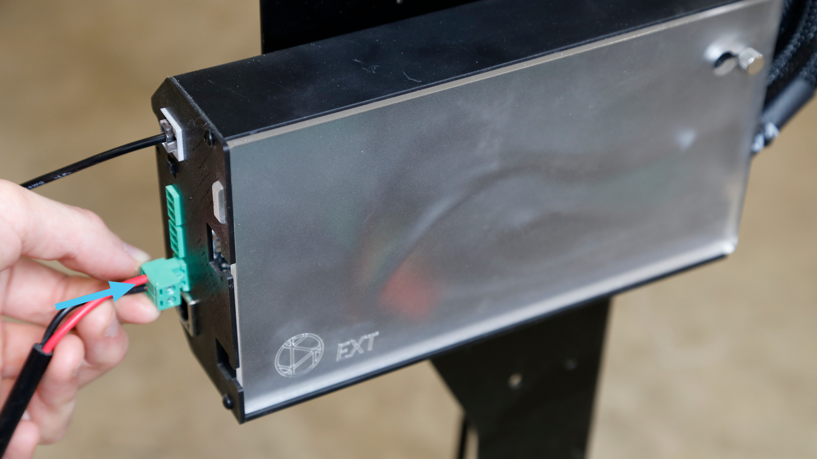
Power supply connector into SLB-EXT
The machine is now put together and you can move onto your first movements. Congratulations!