
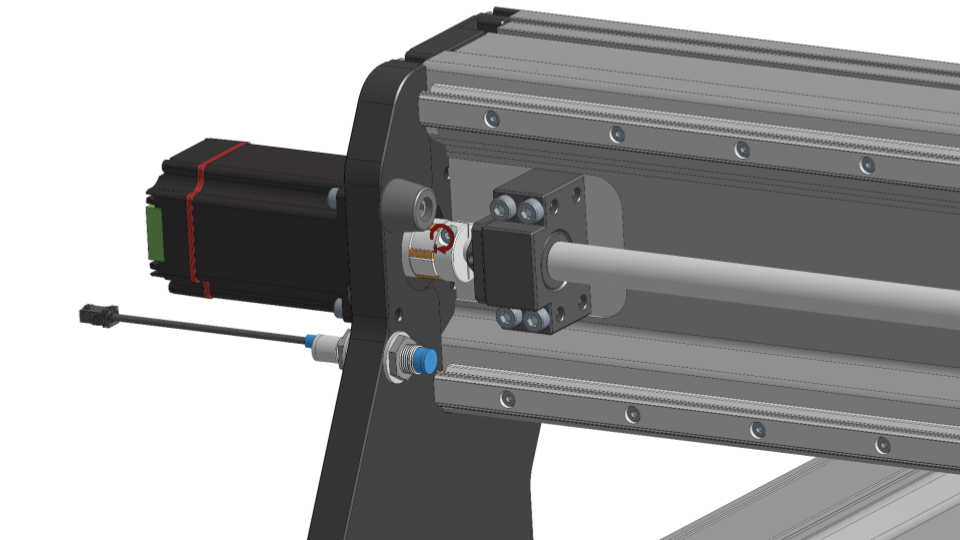
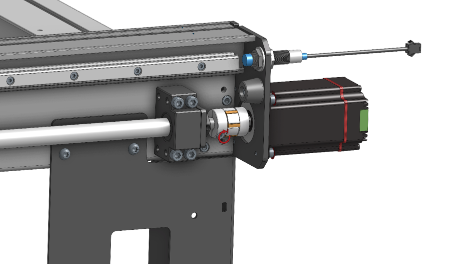
Motor Coupler Installation
The coupler has two different diameter bores: 8mm and 10mm. The 8mm bore fits onto the motor shaft. Install a coupler on each of the three (3) motors. Insert the coupler onto the motor shaft until the coupler bottoms out. It’s important the motor coupler is fully seated, potential damage to the motor can happen with improper installation. Tighten the set screw on the motor side of the coupler to clamp the coupler to the shaft.
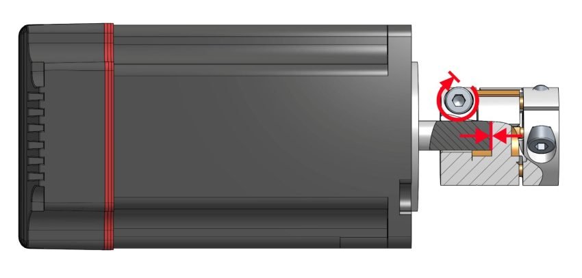
Motor shaft bottomed out inside coupler
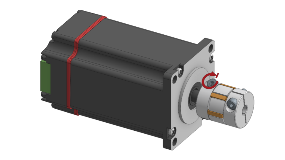
Tighten coupler screw at motor end
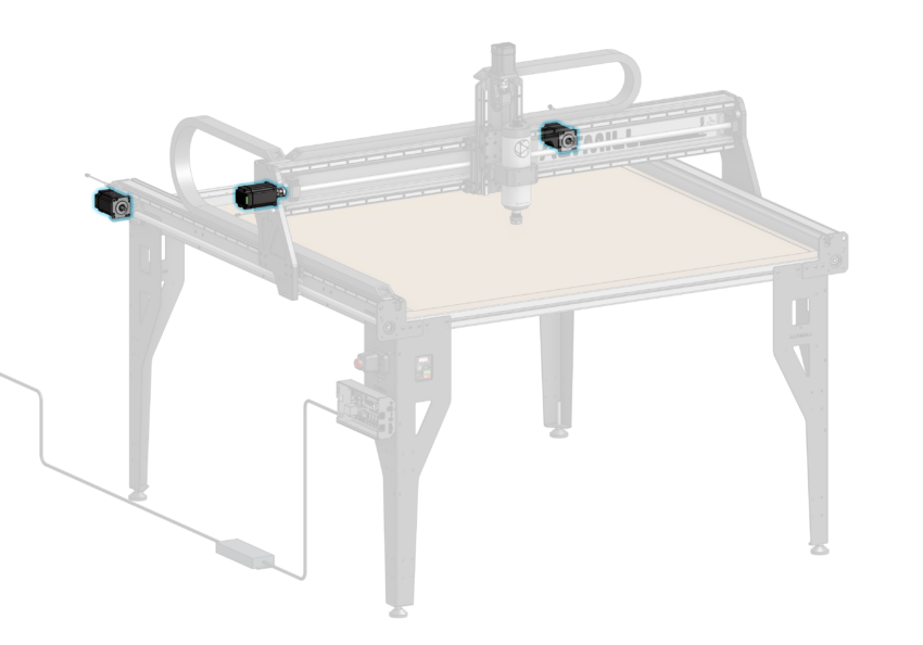
Motor Installation
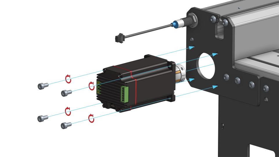
Install a motor with coupler onto the ball screw of the X-axis rail, and fasten the motor to the Y-axis Gantry Plate using four (4) M5-10mm socket head screws. Orient the motor such that the DIP switches are on the bottom.
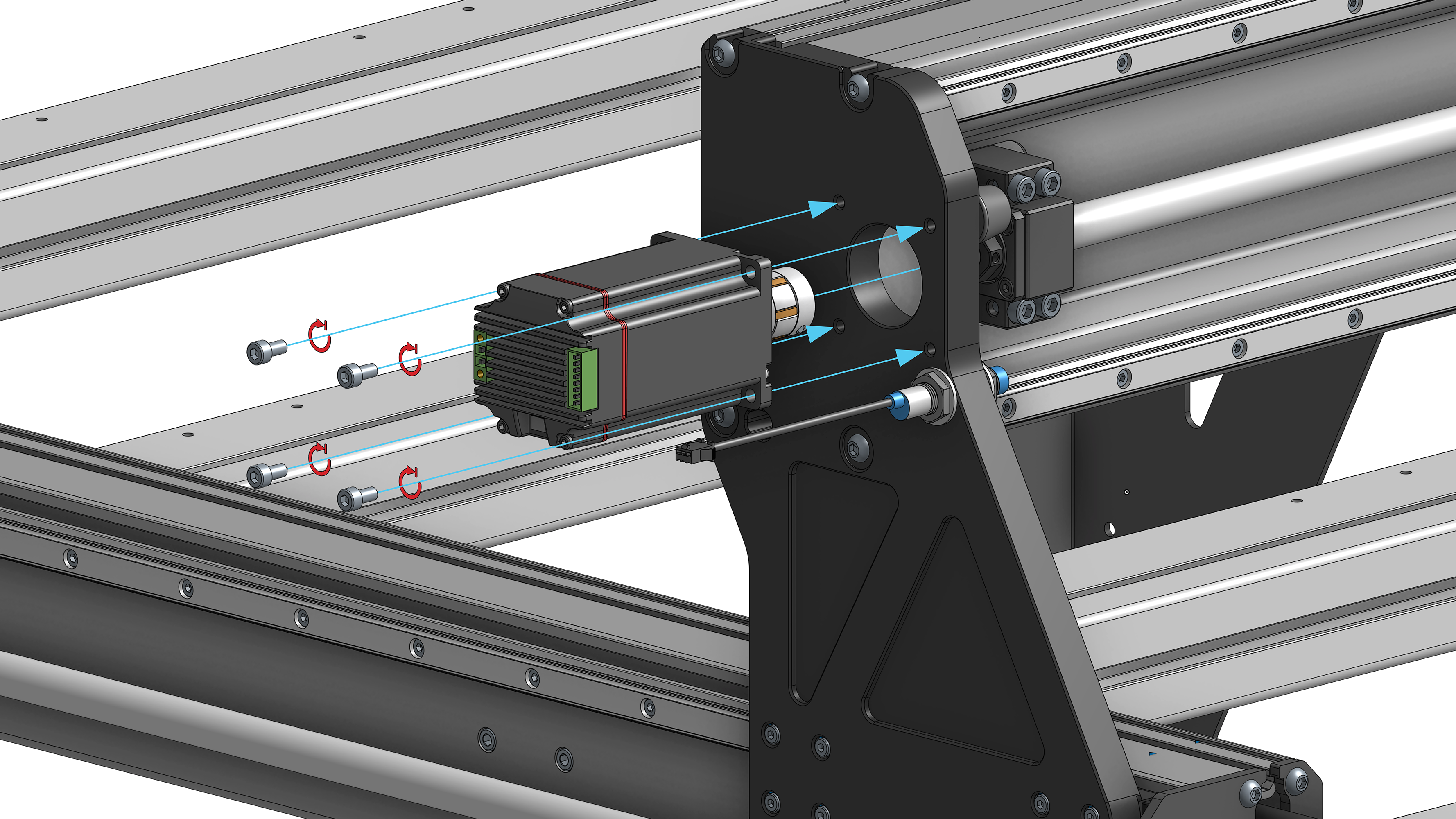
Securely fastening motor onto X-axis ball screw
X-axis Motor orientation
Before tightening the motor coupler, ensure the motor is fully seated onto the y-axis gantry plate. Potential damage to the motor can occur if the motor is not fully seated before tightening. Clamp the coupler to the ball screw shaft by tightening the set screw on the shaft side.
X-axis motor coupler clamping to ball screw
Install the remaining two (2) motors onto the Y-axis ball screws, fastening the motors to the face of the Y-axis end plates using M5-10mm socket head screws. Orient the motor such that the DIP switches are on the bottom.
Securely fastening motor onto Y-axis
Before tightening the motor coupler, ensure the motor is fully seated onto the y-axis gantry plate. Potential damage to the motor can occur if the motor is not fully seated before tightening. Clamp the coupler to the ball screw shaft by tightening the set screw on the shaft side.
Y-axis motor coupler clamping to ball screw
Now that we have our motors mounted, let’s do a final fit check. On both Y-axis sides, ensure that:
1. The motor coupler is centered to the circular cutout on the Y-end plate
2. The table leg does not interfere with the Y-end plate
Please re-assemble the table legs and Y-end plates until the components are properly aligned as specified in the check. You can loosen the fasteners, then slide the components into place before securing them again.
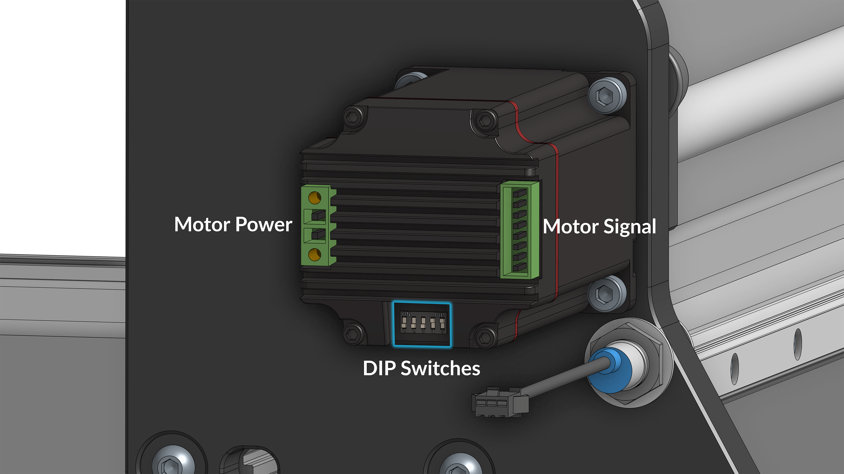
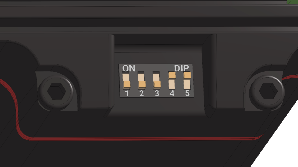
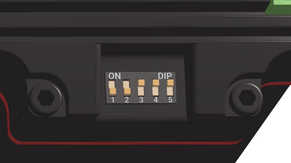
Dip Switches
The motors should arrive with the DIP switches in the correct position for use with the AltMill stock settings.
Check to ensure the DIP switches on the X and Y axis motors follow the order of:
1-5: OFF, OFF, OFF, ON, ON
Correct motor DIP switches setting for X and Y-axis
Then set the Z-axis motor as follows from 1-5: OFF, OFF, ON, ON, ON
Correct motor DIP switches setting for Z-axis
It is highly recommended that you do not change the firmware settings or DIP switch positions, unless you are instructed by Sienci Labs customer support or following instructions for installing another accessory.