
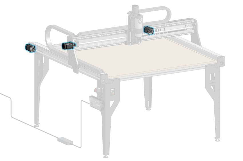
Parts List
- 3x Stepper Motor
- 3x Coupler
- M5-10mm Socket Head Cap Screws
Use one motor and insert the shaft into the coupler until it bottoms out. Securely tighten the M4 set screw on the motor-facing side of the coupler using the smaller 3mm hex key. Repeat this coupler assembly for the remaining two motors.
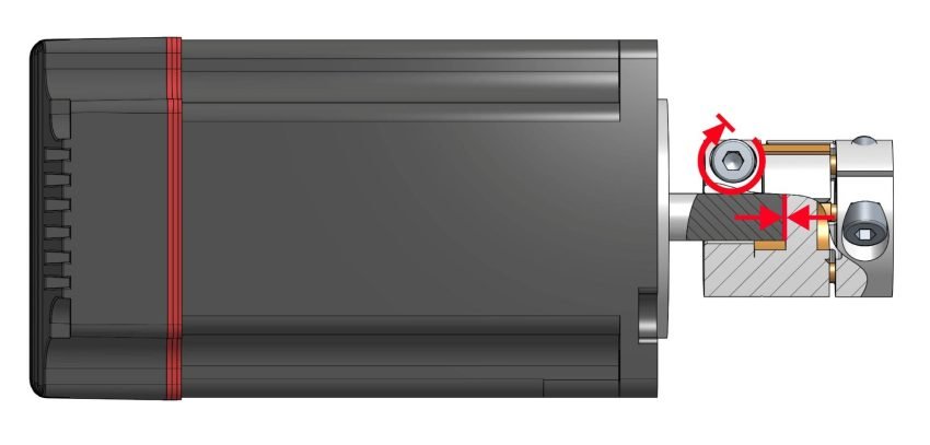
Cross sectional view of coupler and motor, indicating motor shaft bottoming out and motor-facing screw fully tightened
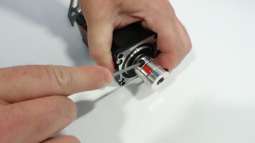
Tightening coupler screw at motor end using Allen key
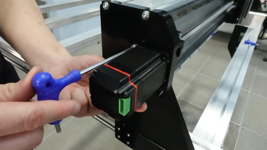
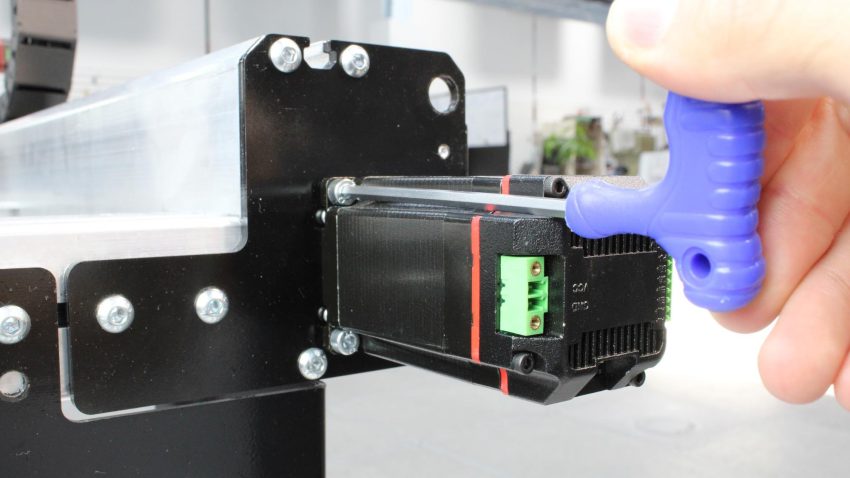
Slide one of the assembled motors onto the X-axis ball screw and install four (4) M5-10mm socket head cap screws into the Y gantry plates and securely tighten. The motors should be mounted so that the DIP switches are facing down.
Securely fastening motor onto X-axis
Closeup showing motor orientation on X-axis
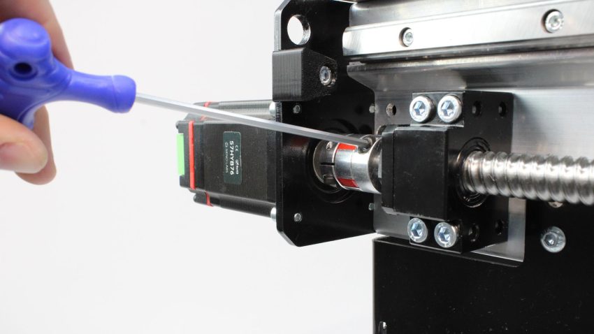
Tighten the coupler set screw at the ball screw end using the smaller 3mm hex wrench.
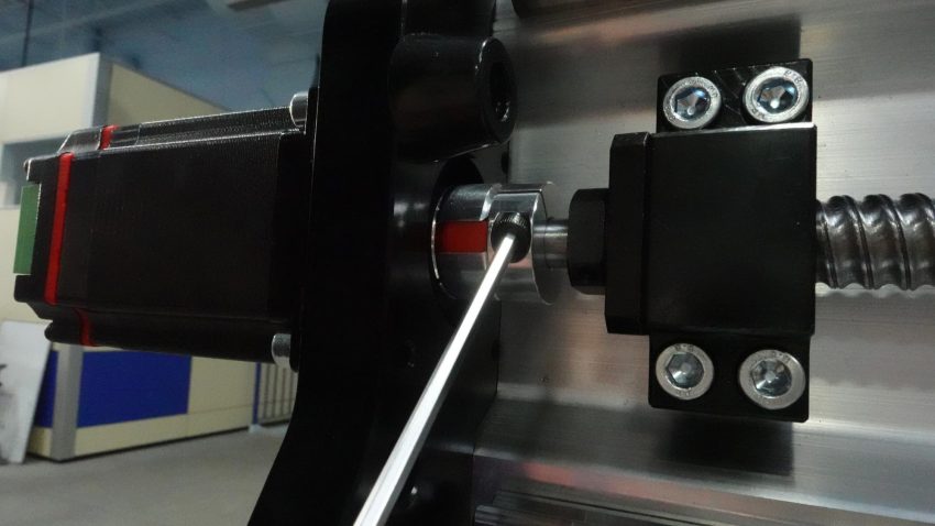
Securely tightening set screw on coupler
Install the remaining two assembled motors onto the back of the Y-axis assemblies using M5-10mm socket head cap screws. When looking at the motors head-on, the motors should be oriented so that the DIP switches are facing down. Do NOT adjust the DIP switches.
Securely fastening motor onto Y-axis, DIP switches facing downwards
Tighten the couplers’ set screw at the ball screw end using the smaller 3mm hex wrench.
Securely tightening set screw on coupler
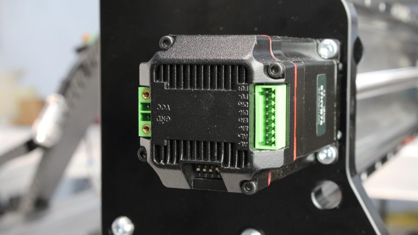
Now we will set the correct DIP switch positions for each motor. Make sure that the X and Y-axis motors are set as follows from 1-5: OFF, OFF, OFF, ON, ON
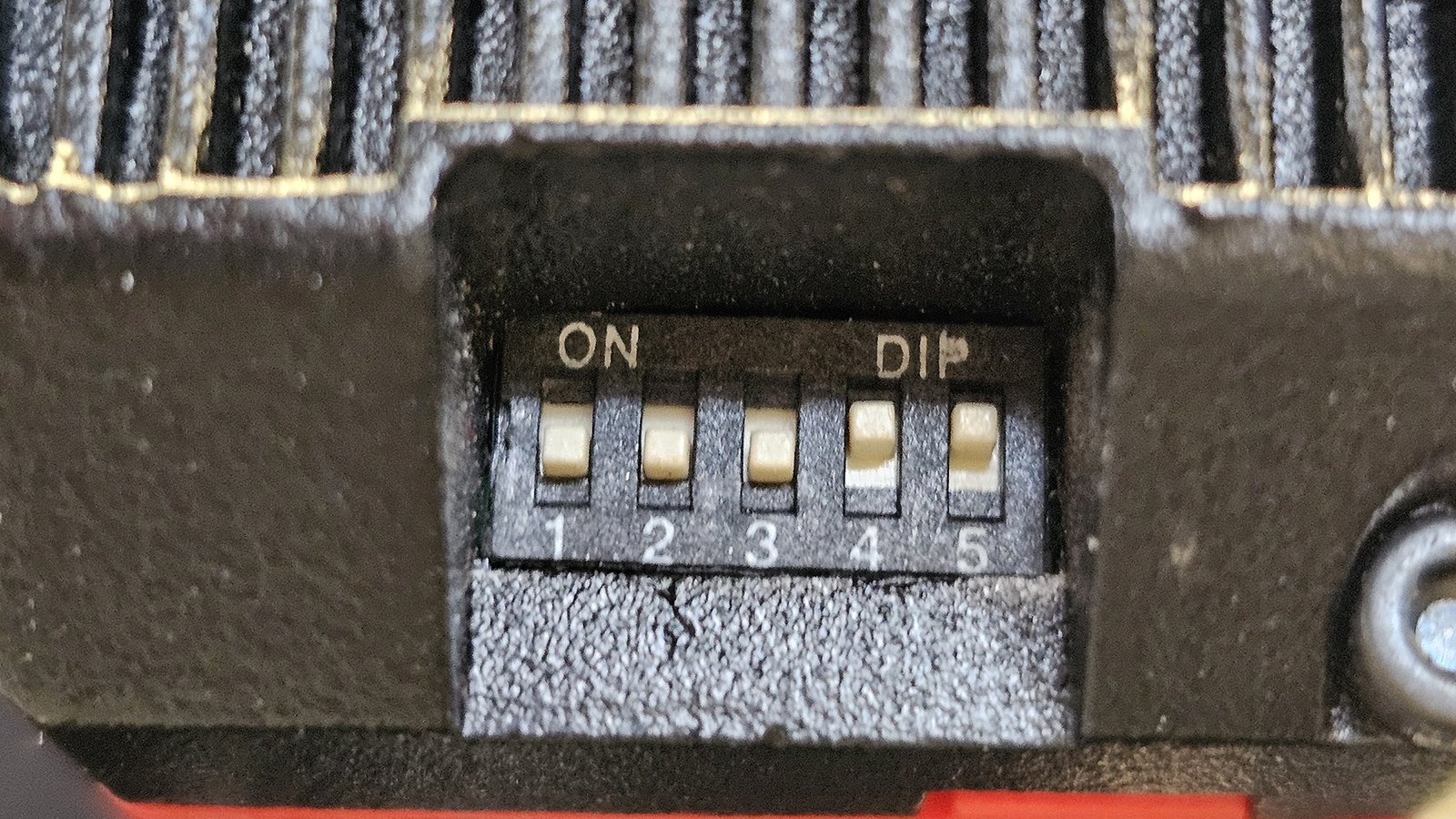
Correct motor DIP switches setting for X and Y-axis
Then set the Z-axis motor as follows from 1-5: OFF, OFF, ON, ON, ON
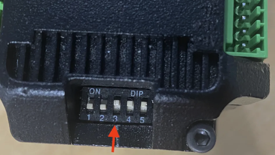
Correct motor DIP switches setting for Z-axis