
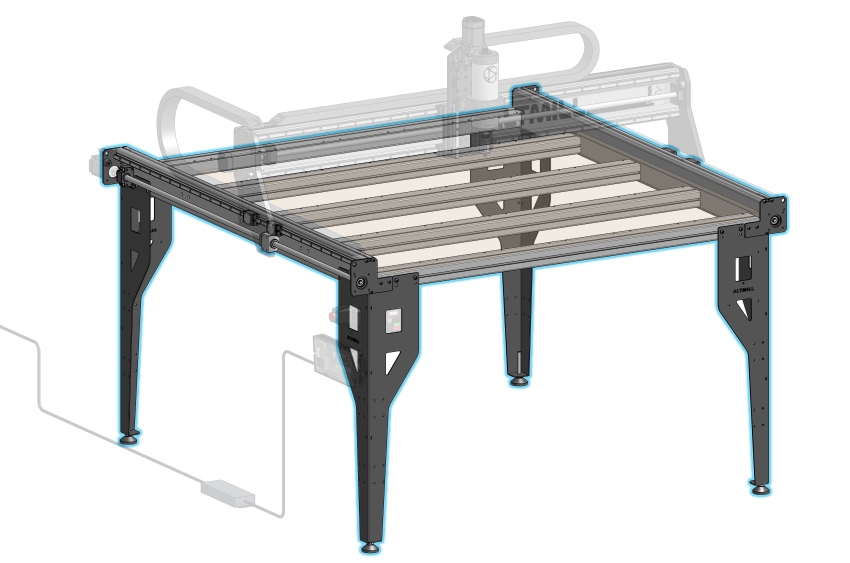
Parts List
- 1x Left Y-Axis Assembly
- 1x Right Y-Axis Assembly
- 5x Crossbeam
- 4x Y-axis End Plate
- 4x Table Leg
- 4x Levelling Foot
- M5-16mm Crossbeam Socket Head Cap Screws (without Loctite)
- M6-10mm Button Head Cap Screws (only for the first 50 AltMill kits)
- M6-12mm Button Head Cap Screws
- M6-16mm Button Head Cap Screws
- M6 Flat Washers
- M6 Roll-in T-nuts
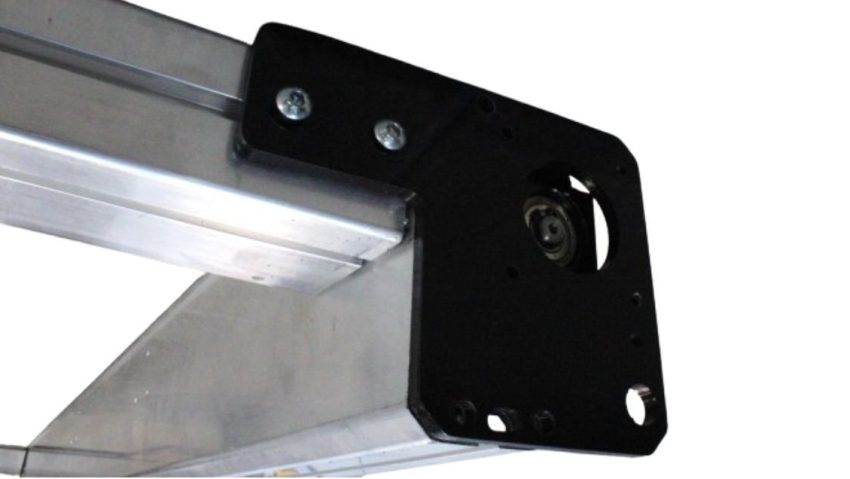
End Plate Preparation
Loosely install the M6-12mm and M6 T-nuts into the four (4) Y end plates.
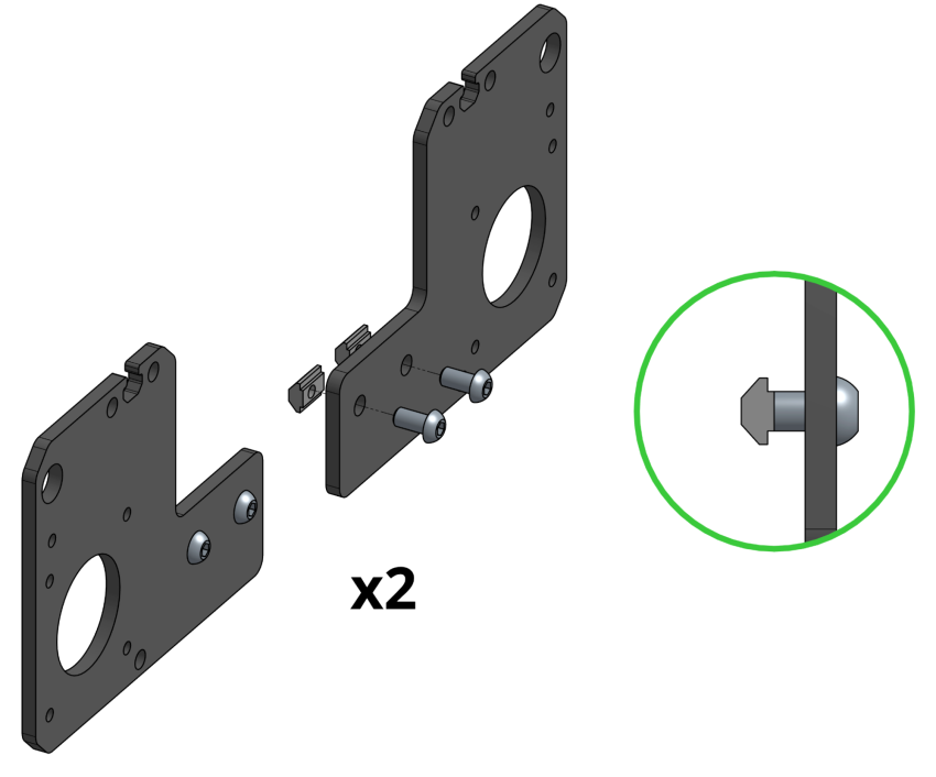
Y end plates with fasteners
Table Frame Assembly
Cross Beam Installation
Lay out the left and right Y rail assemblies and the five (5) crossbeams, either on the floor or on a sufficiently large work table (at least 5’x5’). Ensure the Y-axis assemblies are facing the correct orientation: the ball screw should be facing outwards, away from the 5 crossbeams, and sit below the linear guide rail.
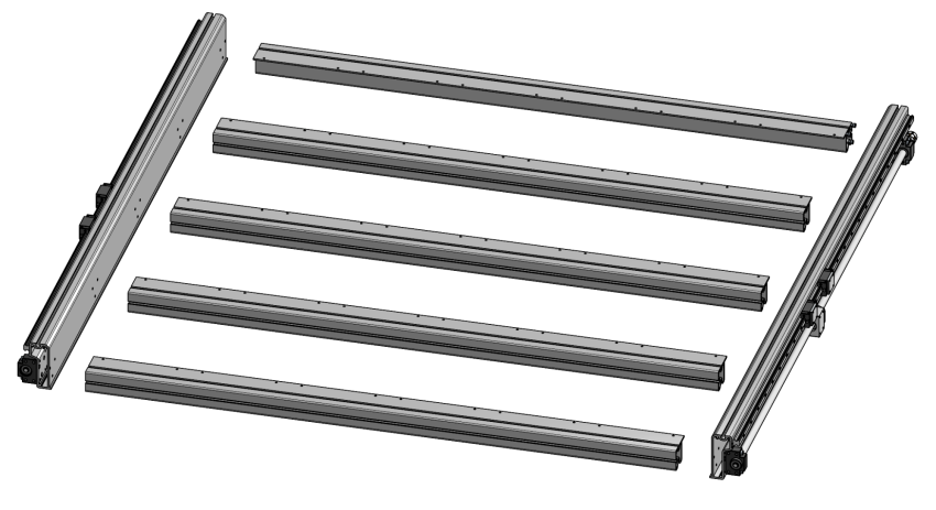
Table layout with crossbeams and Y axes
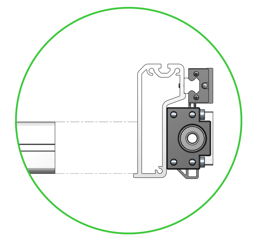
Alignment between Y-axis and crossbeam
Slide the T-nuts of the four pre-assembled Y end plates into the ends of the front and rear crossbeams. Note the orientation of these parts as they are mirrored left and right.
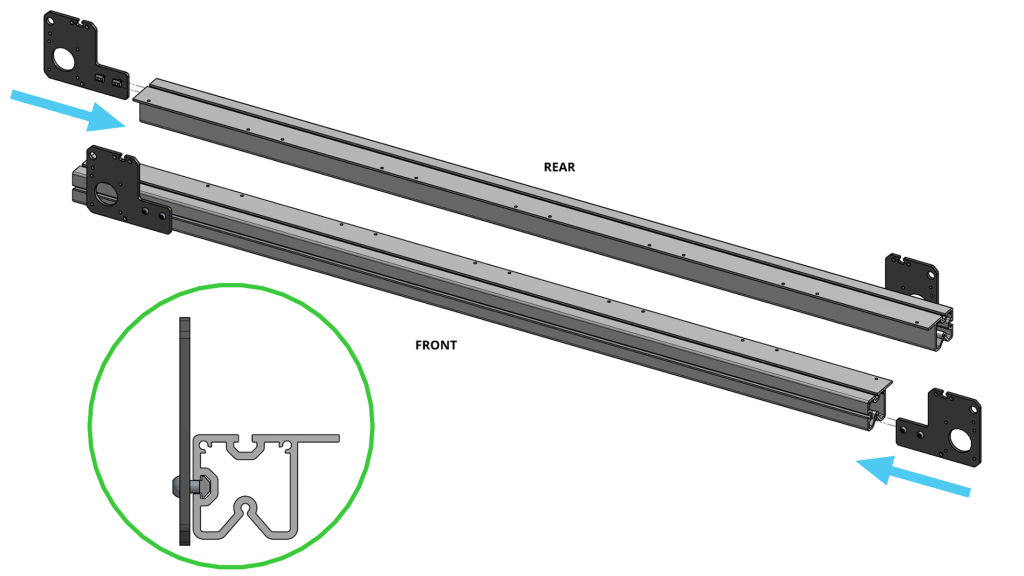
Front and rear crossbeams with Y end plates
Note the orientation of the front crossbeam and rear crossbeam. The flanges must be facing towards the center of the machine. For the middle three (3) crossbeams, the orientation doesn’t matter. Use one of the cardboard inserts to act as a spacer, raising the crossbeam to make installation of the hardware easier.
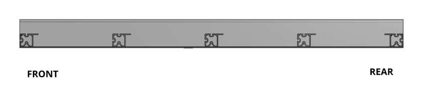
Side view of crossbeams
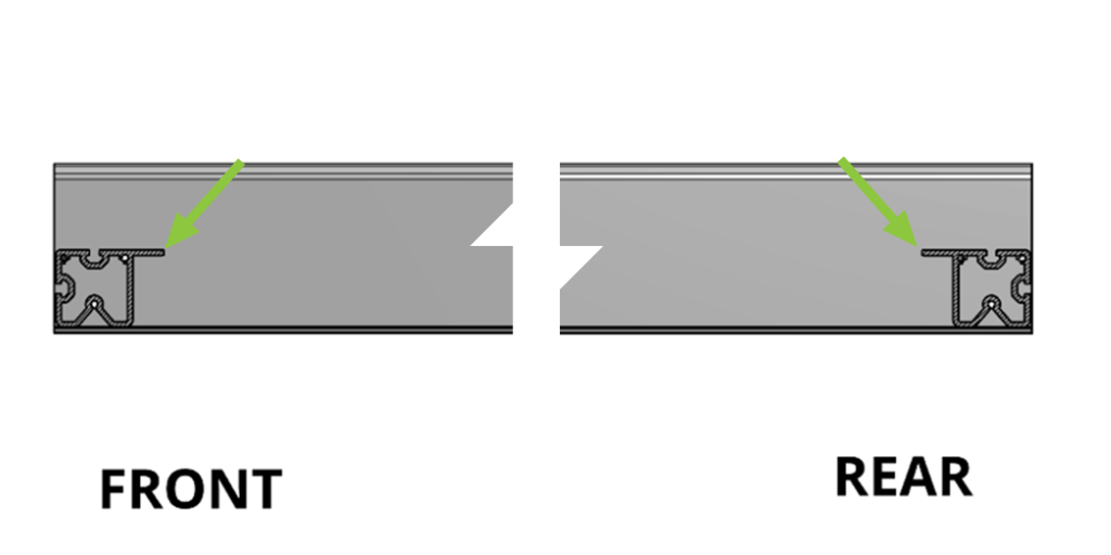
Side view of front and rear crossbeams showing flange direction
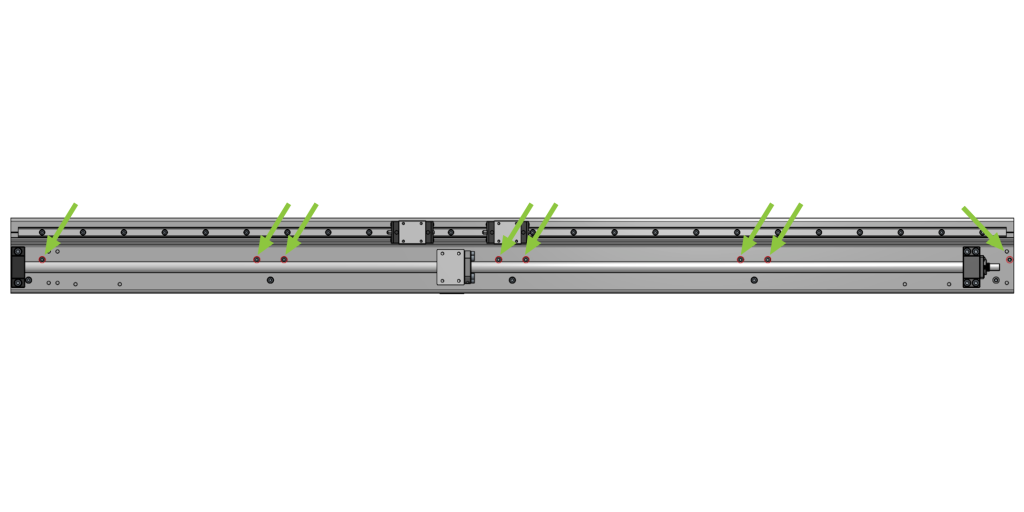
Starting on either the left or right, insert M5-16mm socket head cap screws (with Loctite) through the Y rail into the top row of holes on the crossbeam. Tighten all screws loosely, so that the hardware is easier to see. There should be eight (8) screws fastened.
Fastening the crossbeam to Y rail
Repeat the previous step on the other side.
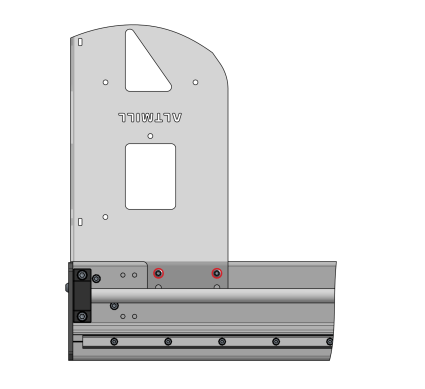
Side view of Y rail indicating location of mounting holes to crossbeams
Once all crossbeams have been loosely installed you can now fully tighten all fasteners in preparation to flip the table forwards.
With a helper, flip the table over so the ball screws are now above the linear guides. Now is a great time to pick up any dropped screws that may have fallen into the Y-axis assembly.
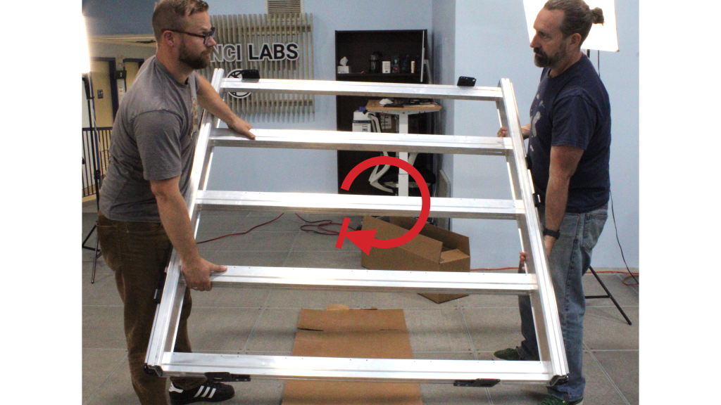
Table flipped forward to mount end plates and first set of legs
Finish installing the M5-16mm socket head cap screws into the remaining top holes for each of the crossbeams. Secure until snug. There should be five (5) new screws fastened on each side.
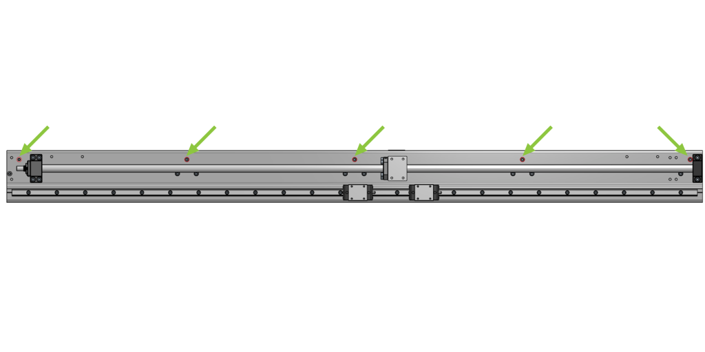
Side view of Y rail indicating location of remaining mounting holes after table flip
Move the four (4) Y end plates onto the outer corners of the crossbeam, making sure they are positioned so that the holes on the end plates are aligned with the Y rail. Loosely fasten to keep them in place.
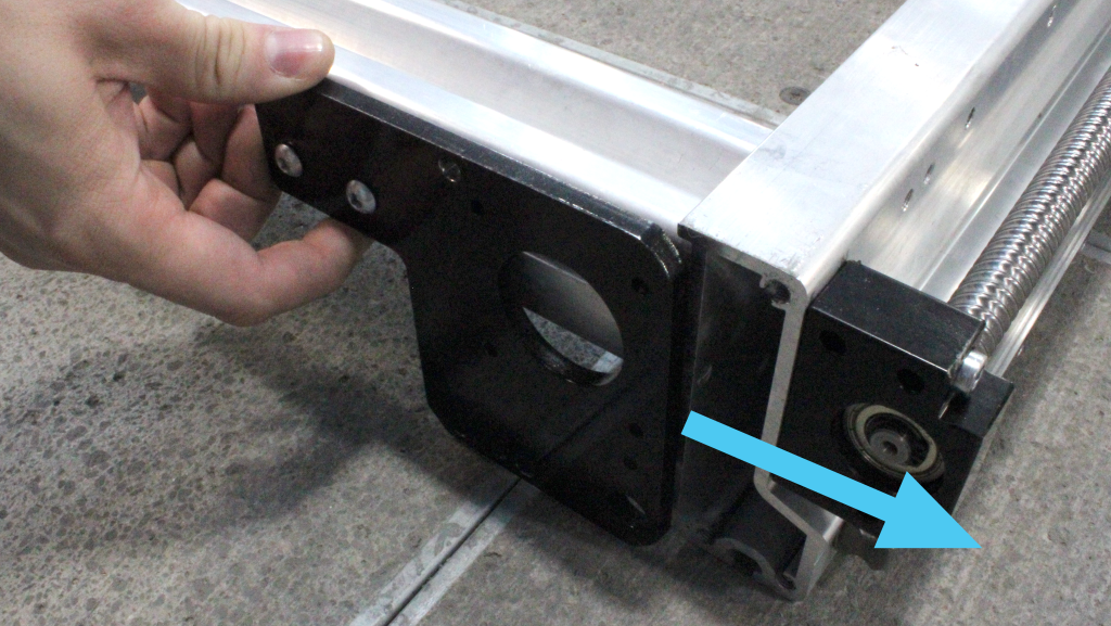
Moving end plate to one corner of the table
Aligning end plate to the holes on the Y rail
Table Legs Assembly
Take the leveling foot and remove the top hex nut. Rotate the middle adjusting hex nut all the way to the bottom. Pass the threaded stud of the foot through one of the legs from the bottom, then reinstall the top hex nut over the hole, loosely securing the foot. Repeat for the remaining 3 feet.
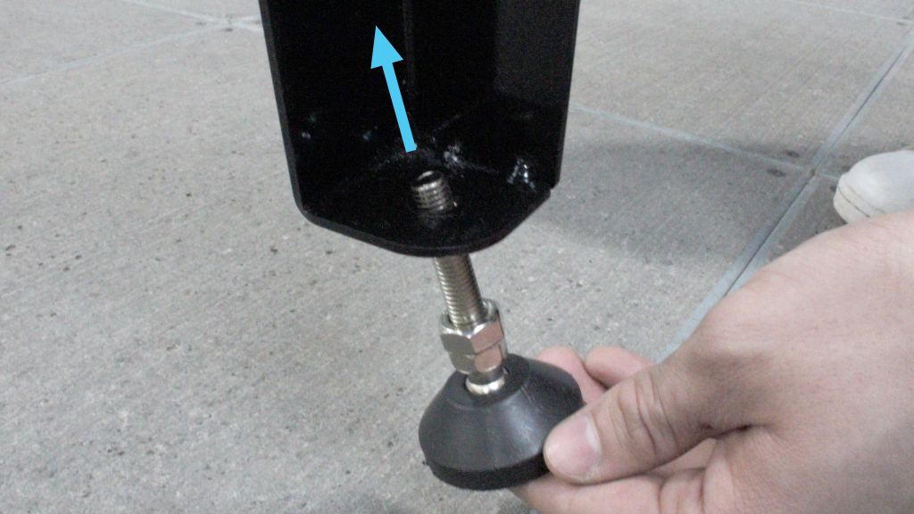
Inserting threaded stud into table leg with top hex nut removed
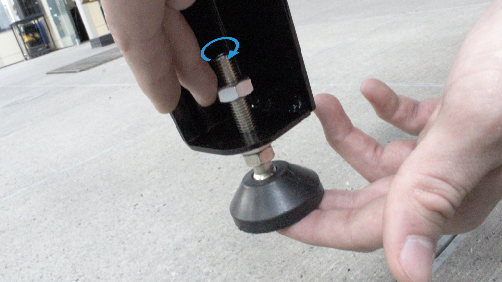
Reinstalling top hex nut to secure foot
If you are tight on space, start this left and right leg installation at the most constrained side of your workspace as shown in the illustration below. You may want to rotate your table accordingly.
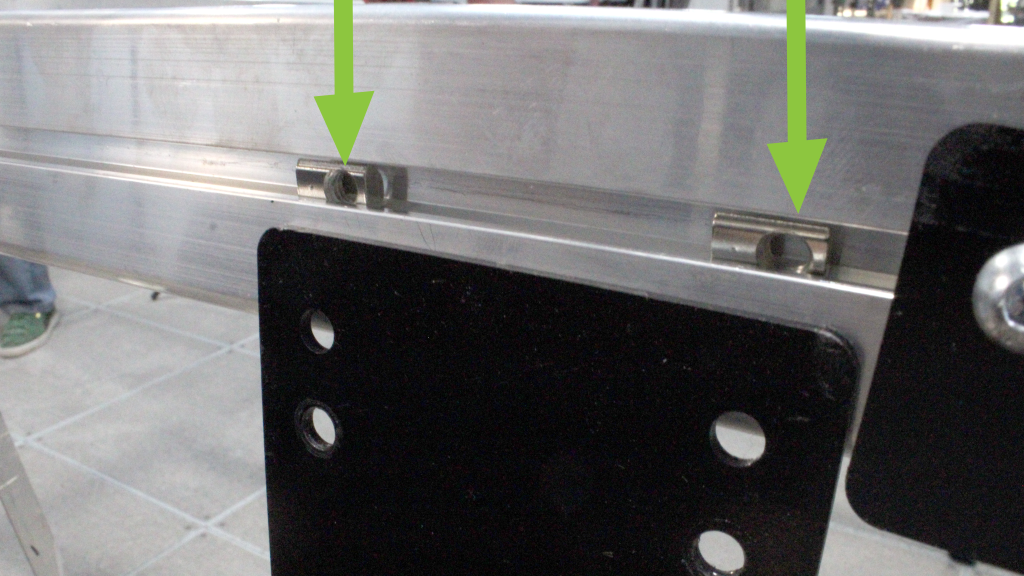
Starting with the right leg, insert two (2) M6 roll-in T-nuts into the T-slot on the outwards face of the relevant crossbeam at the right end of your table. Make sure the flat side of the T-slot is facing out so that a screw can be threaded in.
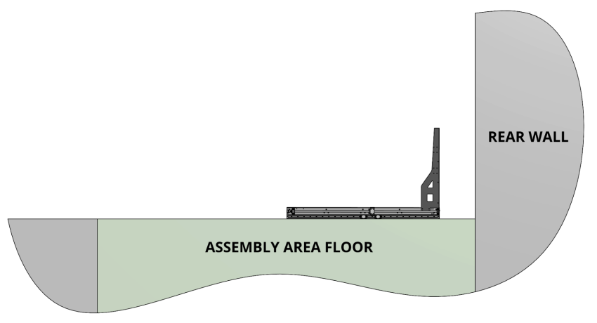
First set of table legs should be installed at the side with the least space
Inserting M6 Roll-in T-nut into the T-slot at the outward face of the crossbeam
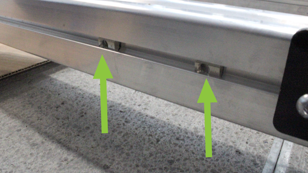
Location of T-nuts on crossbeam
Take one leg and place it upright at the corner of the frame. Align the two lowest mounting holes on the leg with the T-nuts. You can use the allen key to move the T-nuts into position. Use two (2) M6-12mm button head cap screws, with two (2) M6 washers to loosely fasten the leg; it should be sitting against the end plate.
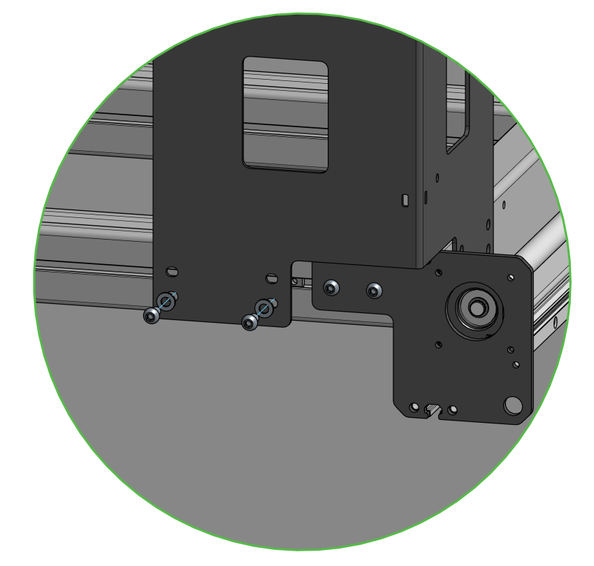
Table leg loosely secured and positioned against end plate
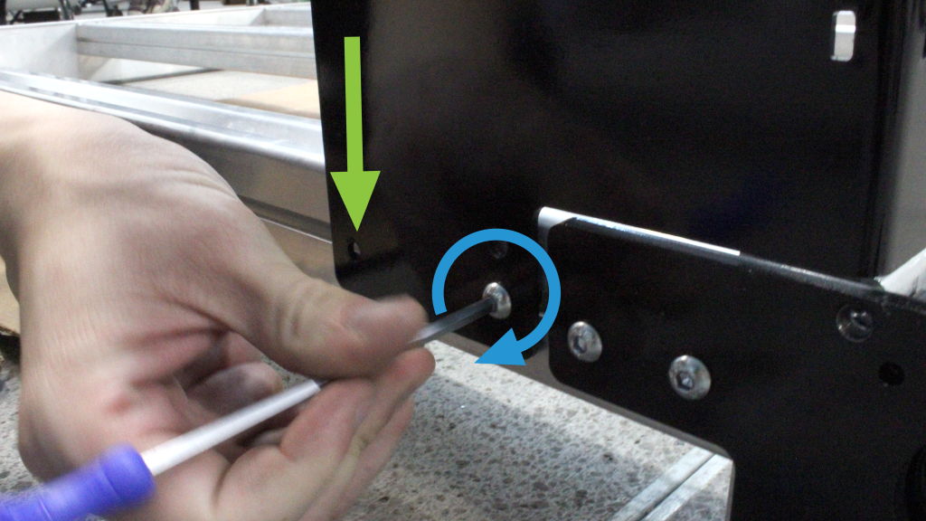
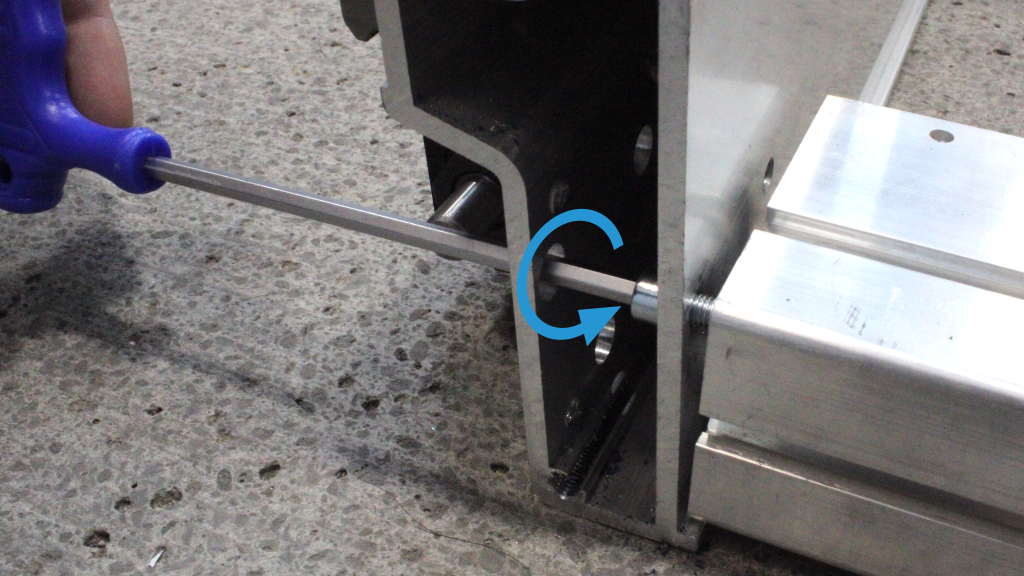
Fastening table leg screws with manual screwdriver
With two (2) M6-12mm button head cap screws, loosely secure the other side of the leg onto the frame without washers. Then, fully tighten all four (4) M6 screws on both sides of the right leg. Repeat steps for the left end of the table.
Location of screws on other side of the table leg
With a helper or on your own, lift the end of the table with the two legs installed, then walk over to flip onto the other side, guiding it to rest on the two legs.
Flipping table to rest on its two assembled legs
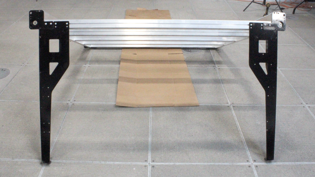
Table resting on its two assembled legs
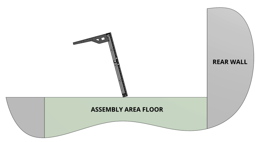
Table flipped towards the more spacious side of the workspace
Using a sawhorse, the smallest shipping carton placed on its side (36”x10”x10” box) or another sturdy support, prop up the other side for the remaining leg installation.
Using a small ladder to stand the table up
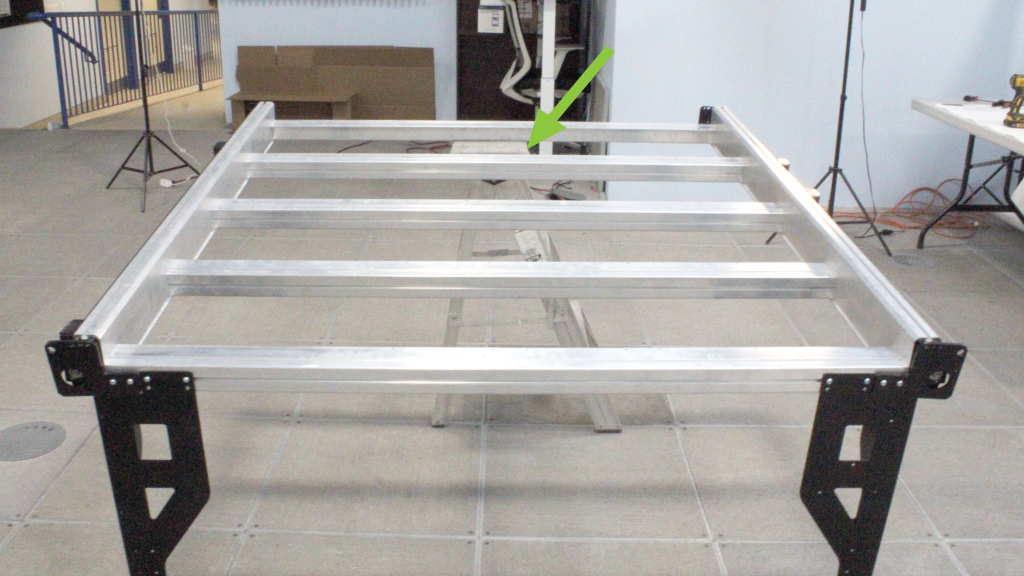
Table supported by a small ladder
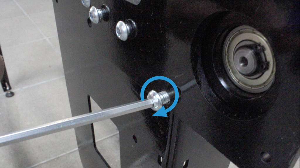
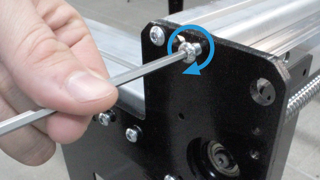
Repeat the previous steps to install the final two table legs. Install the T-nuts, align and fasten the leg with two (2) M6-10mm OR M6-12mm button head cap screws, using the row of holes closest to the leg edge. Loosely tighten. Install two (2) M6-12mm button head cap screws through the lower row of holes in the table leg and into the Y rail. Then tighten all hardware on the table leg until snug.
Aligning remaining table leg with T-nuts
Fully fastening remaining table leg with manual screwdriver
Fully fastening other side of remaining table leg with manual screwdriver
Final Adjustments
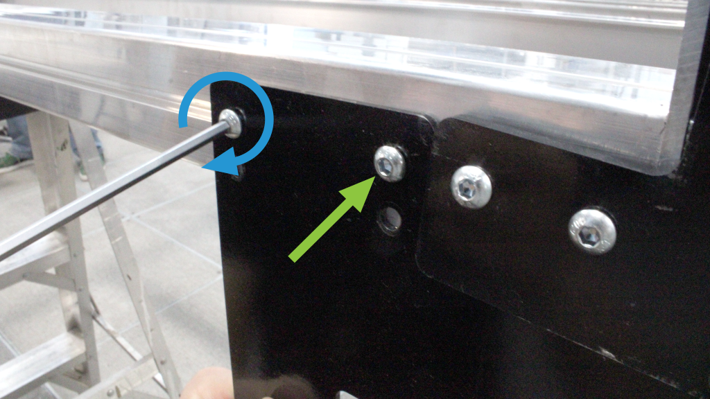
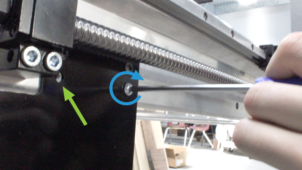
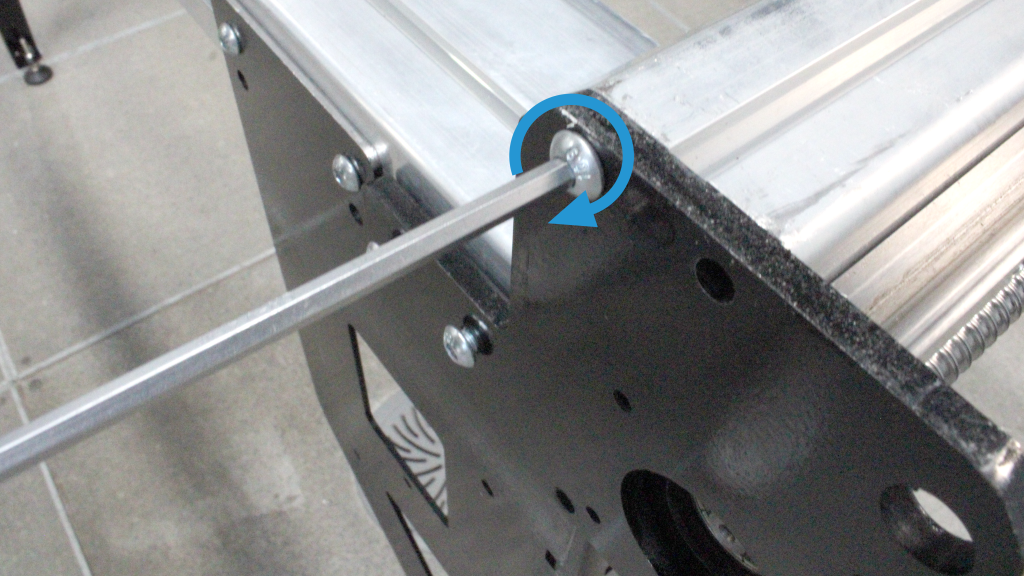
Using three (3) M6-16mm button head cap screws, loosely fasten the Y end plates to the ends of both Y rails. Securely tighten the two (2) M6-10mm OR M6-12mm button head cap screws previously installed into the T-slot of the crossbeams, at all four corners of the machine.
Loosely fastening first screw on end plate to Y rail
Loosely fastening second screw on end plate to Y rail
Loosely fastening last screw on end plate to Y rail
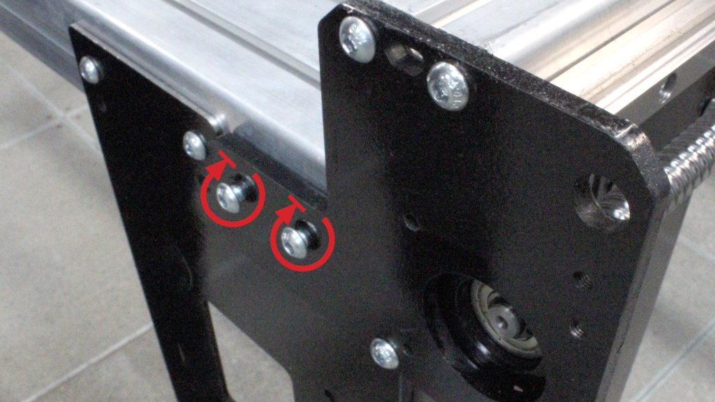
Tightly fastening screws connecting crossbeam to leg
Then, fully fasten the three (3) button head screws connecting the Y end plates to the Y-axis rails. Make sure to do this for all four corners of the machine.
Now is a good time to put your machine into position and to level the legs front to back, left to right, by adjusting where the hex nuts sit on each of the levelling feet. The side of the included wrench, along with a 17mm or adjustable wrench can be used to tighten these nuts.
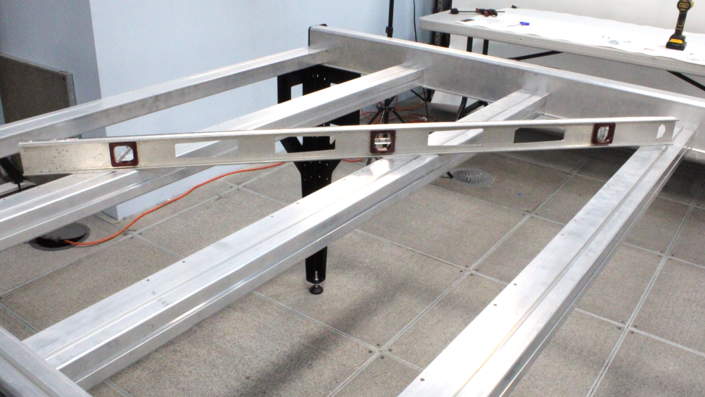
Checking the table levelness
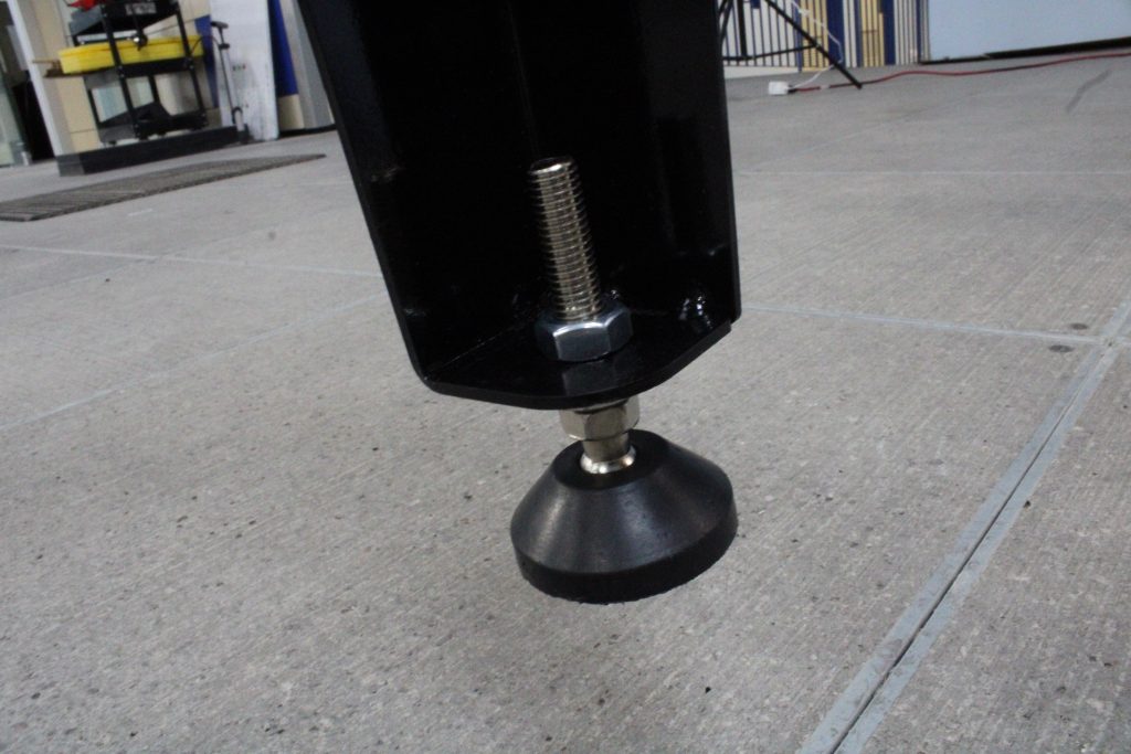
Completed table foot installation
Pat yourself on the back and stop for a break, the most difficult (and exhausting) part of assembling the AltMill is all done!