
Parts List
- 4x Inductive Sensor
- 4x Motor Cable
- 1x Spindle Cable
- 1x 1.5KW Spindle
- 1x VFD Unit
- 2x Drag Chain
- 10x Cable Hanger Clip
- Zip Ties
Inductive Sensor Mounting
Take one inductive sensor, and thread a nut onto it approximately 3/4” (20mm) from the sensor end. To do this easily, use the flat-to-flat width of another nut as the offset distance from the sensor end to the threaded nut, as shown below. This will be the Z-axis sensor.
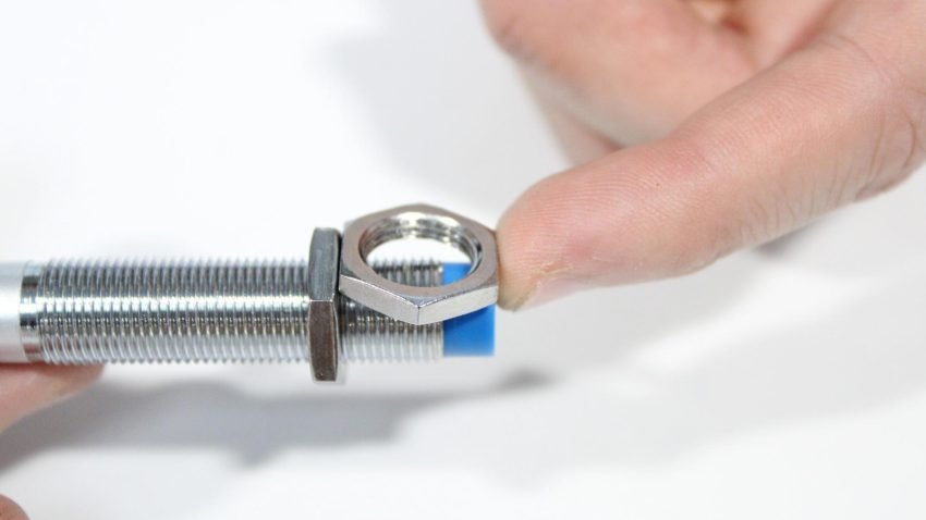
Using loose hex nut as offset between sensor end and threaded nut
Install a lock washer onto the Z-axis sensor as shown.
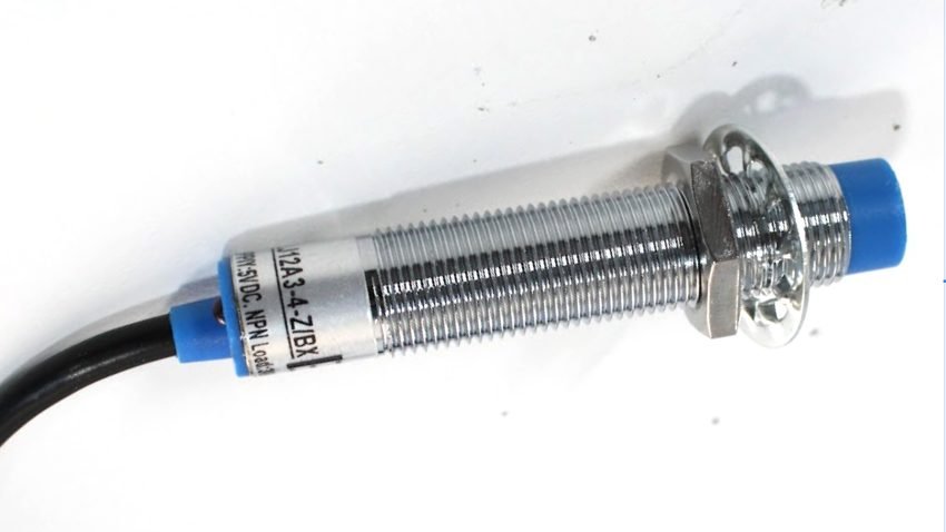
Assembled Z-axis inductive sensor
Place the Z-axis sensor through the rear of the Z-axis assembly, so that the sensor end is flush to the front of the X carriage face, just behind the ball screw.
Then, install a flat hex nut at the front to secure the sensor, and thread this on as much as you can with one finger. Make sure you’re only rotating the front nut, and not the entire sensor or the rear nut.
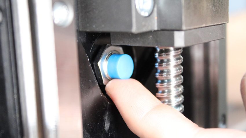
Installed hex nut on the Z-axis sensor
Sensor end is flush to the X carriage face
Take the remaining three inductive sensors and thread one nut, then one washer onto the end of each one; these will be adjusted in following steps.
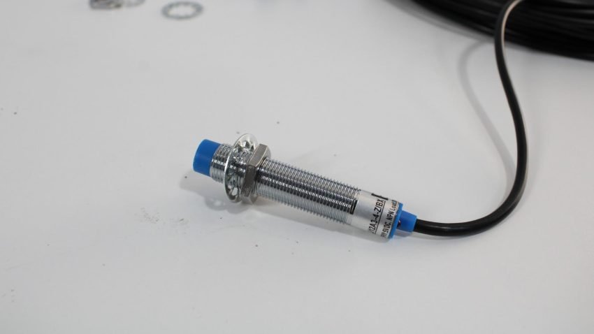
Assembled inductive sensor
Take two of the sensors and install them through the openings on the left and right Y end plates, at the back of the machine.
Mounting sensor onto Y end plate
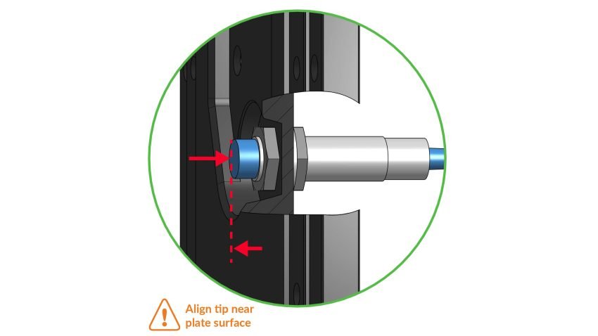
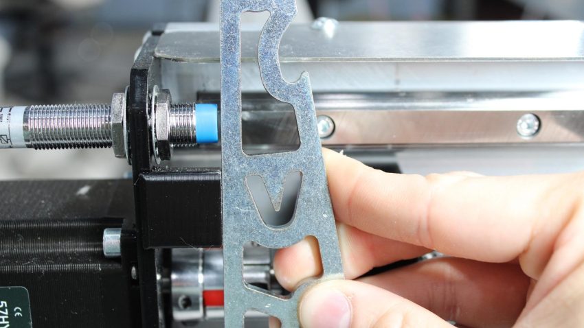
Position the two sensors at the end plates, so they sit just 1-2mm before the bump stop. Make sure the left and right Y sensors match, meaning they are the same distance offset from their end plate. You can use the included wrench as a straight edge, resting against the bump stop. For each Y sensor, add a lock washer, then another hex nut to secure, therefore sandwiching the end plate. Tighten the nuts fully. Leave the wires free for now.
Sensor at Y end plate, offset 1mm from bump stop
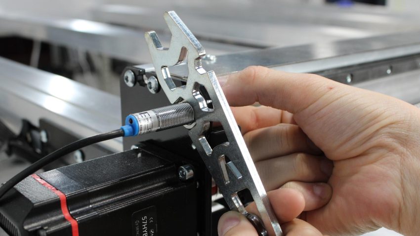
Using AltMill wrench to tighten hex nut at Y sensor
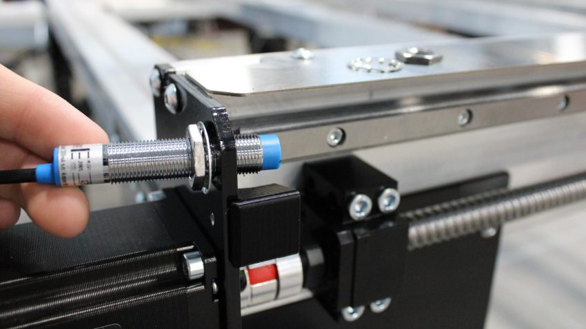
Place the remaining sensor into the opening on the left Y gantry. This will be the X-axis sensor.
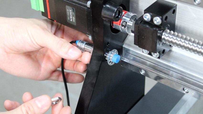
Mounting X sensor onto Y gantry
Similar to the Y-axis, align the end of the sensor 1mm before the bump stop. Add a lock washer, then thread a nut on. Fasten nuts with the wrench until secure, sandwiching the Y gantry as the sensor is fixed in place. Leave the wire free for now.
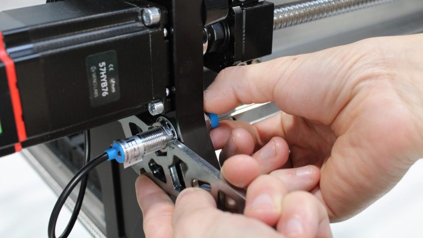
Using AltMill wrench to secure the hex nut on Y sensor
Y-axis Cable Routing
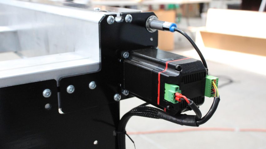
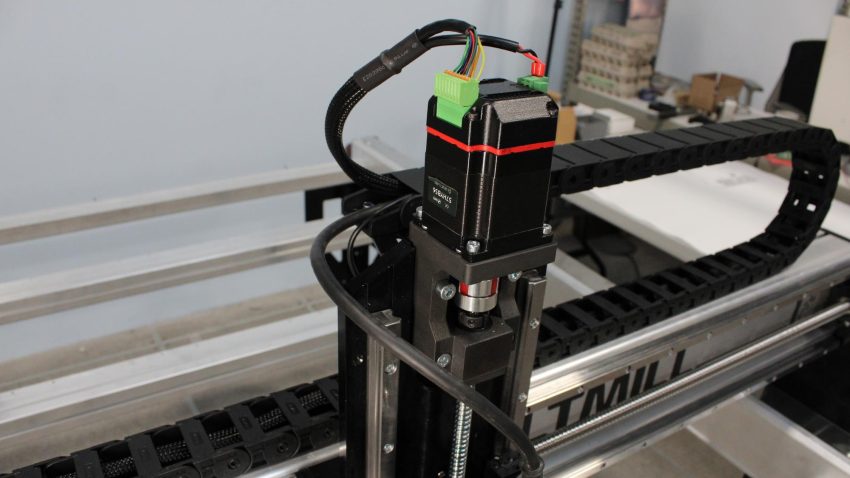
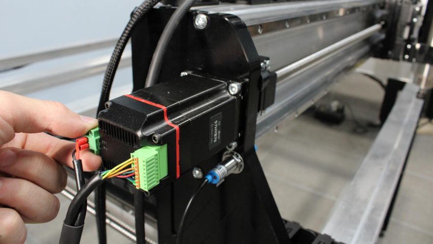
Grab one motor cable and locate the end with two green connectors. Plug these into the matching connectors of the motor located on the back left of the machine.
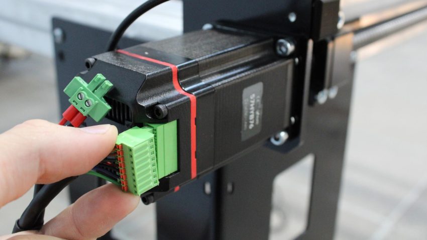
Plugging matching connectors into back left motor
For each connection, use a small flathead screwdriver to fasten the locking screws for the power connector.
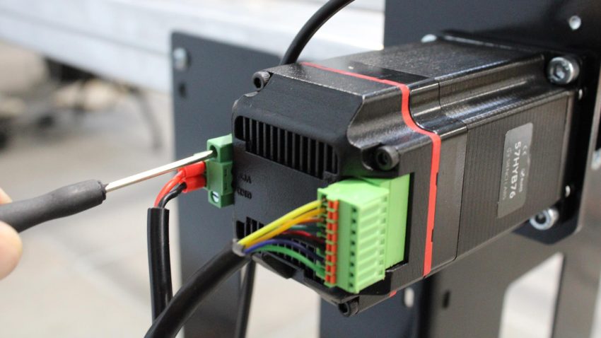
Securing power connector with flat head screwdriver
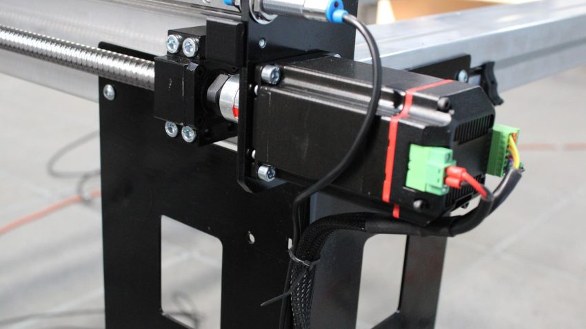
Grab another motor cable and repeat the previous steps for the back right motor on the machine.
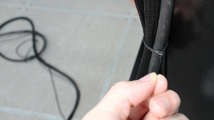
Thread a zip tie through the two slots in the back right leg. Secure the motor cable and inductive sensor cable to the leg.
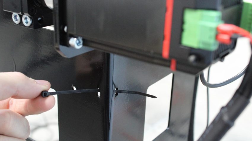
Threading zip tie through slots on back right leg
Motor cable and sensor cable secured onto back right leg
Repeat this at the back left corner of the machine, securing the motor and inductive sensor cables to the table leg.
Motor cable and sensor cable secured onto back left leg
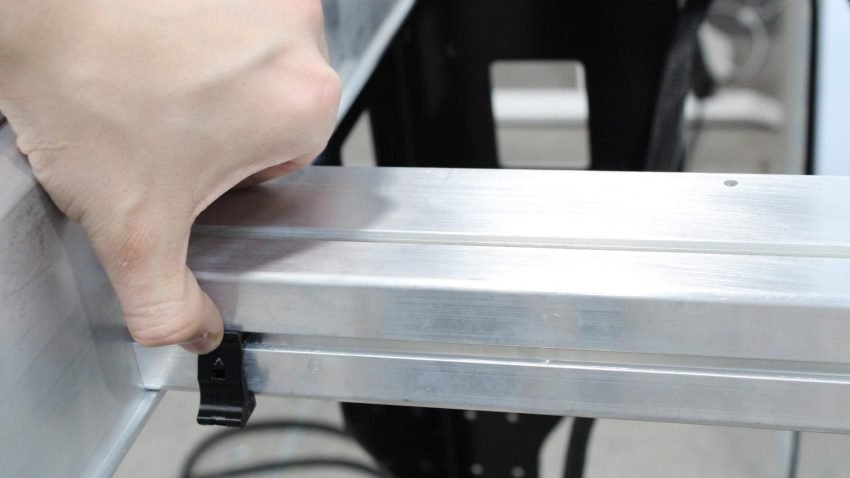
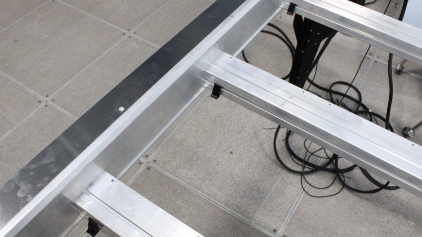
Grab three (3) of the cable hanger clips, then snap them into the rear crossbeam at the positions shown below, by pressing firmly on the face opposite of the prongs
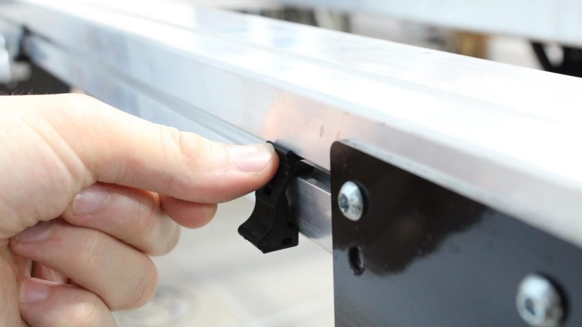
Cable hanger clip pressed into T-slot channel on rear crossbeam
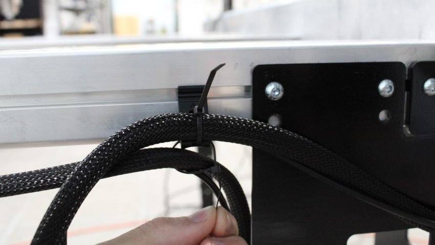
Thread a zip tie through the two small holes on each cable hanger clip mounted on the rear crossbeam
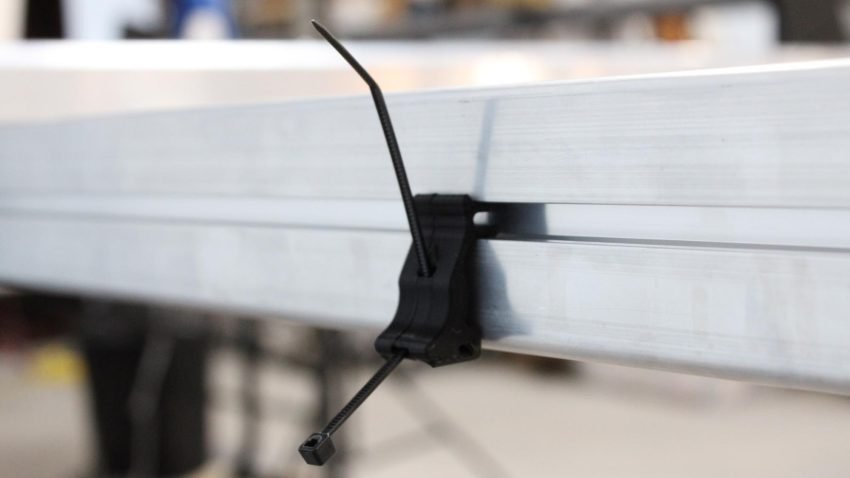
Zip tie in cable hanger clip on rear crossbeam
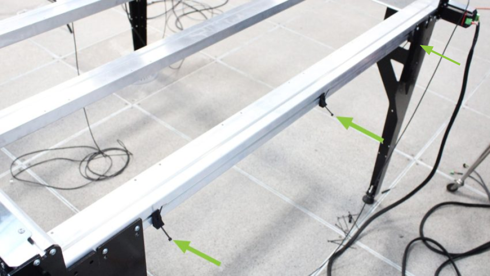
Location of cable hanger clips on rear crossbeam
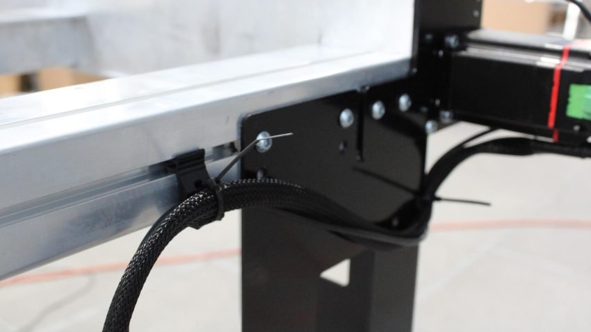
From the back right corner, secure the cables using the two closest hanger clips and zip ties.
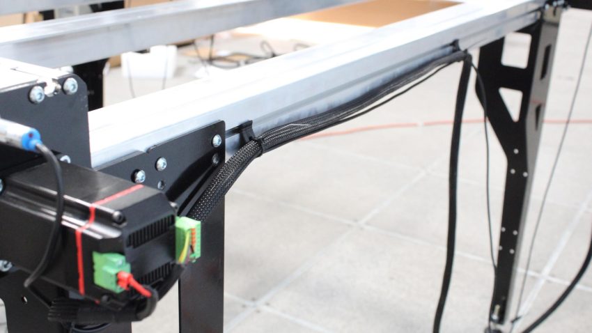
Cables on back right side anchored by two hanger clips
From the back left corner, secure the cables using the closest hanger clip and zip tie.
Cables on back left side anchored by one hanger clip
Using the hanger clip for the back left cables, insert a second zip tie into this clip. Bring the cables coming from the back right of the machine, so that both sets of cables cross over one another and form one bundle, a total of 4 cables. Fasten using the second zip tie.
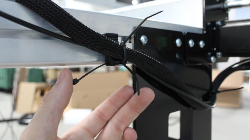
Second zip tie threaded into hanger clip with back left cables
Cables bundled by second zip tie on hanger clip
Attach one cable hanger clip to each front face of the three (3) middle crossbeams, on the left side.
Snapping cable hanger clip on the left side of a middle crossbeam
Location of hanger clips on middle crossbeams
Install zip ties onto the three clips, then use them to secure all cables coming from the rear of the machine.
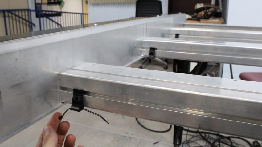
Zip tie in cable hanger clip on a middle crossbeam
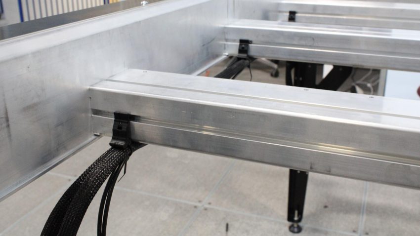
Hanger clips on middle crossbeams securing rear cables
Side view of middle crossbeams with secured rear cables
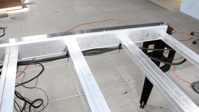
Grab the unsecured lengths of the cable bunch, and bring these towards the rear of the machine, so they’re out of the way while the cable drag chains are installed. We’ll come back to them later.
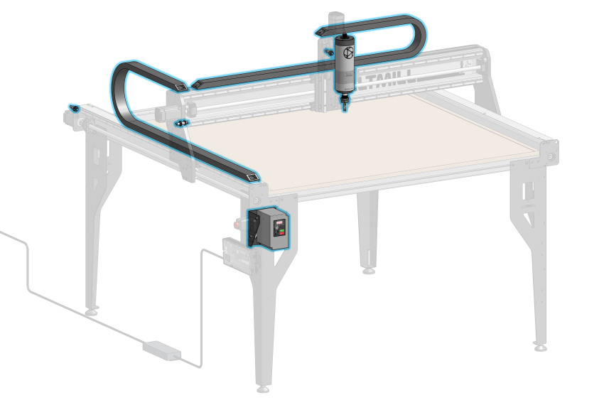
Spindle and VFD Installation
If you purchased the Sienci Labs Spindle kit, then open the Spindle Kit box and take out the spindle and VFD unit. Otherwise, if you are installing your own 80mm spindle, have it ready on hand along with any other accessories.
On the VFD unit, align the VFD mounting bracket with the holes as shown. Using two (2) M5-16mm socket head cap screws and two M5 nylock nuts, secure the VFD unit onto the bracket. Use the included wrench to hold the M5 nuts in place.
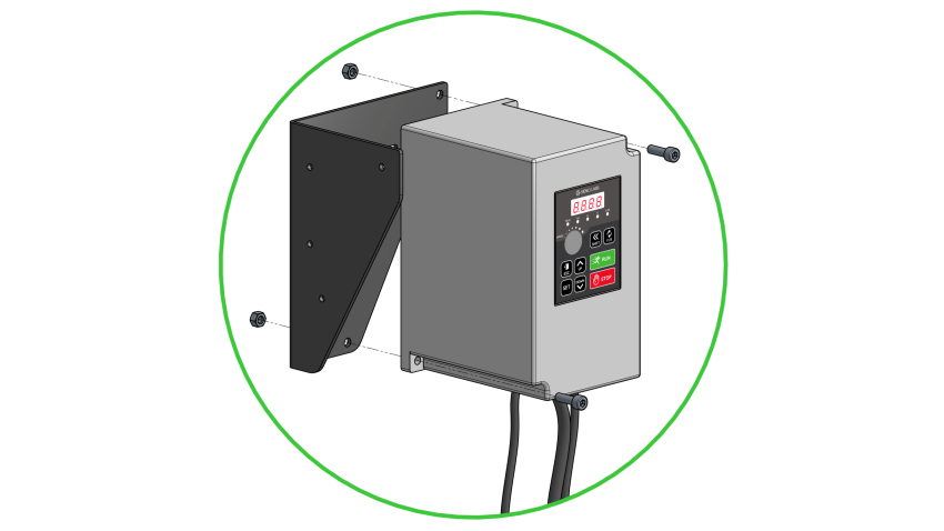
Aligning holes between VFD unit and mounting bracket
Mount the VFD unit onto the inner walls of the front left table leg, orienting it so that the control panel is accessible from the cutout on the leg. Use two (2) M5-16mm socket head cap screws to secure the VFD bracket onto the leg.
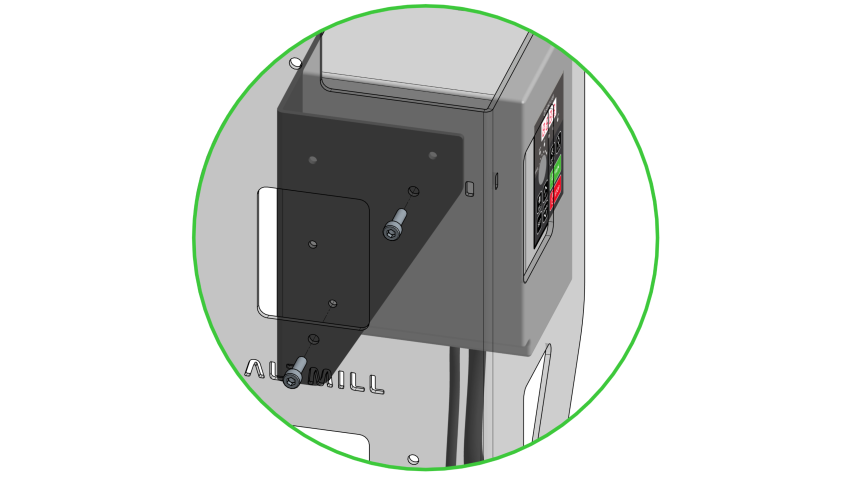
Fastening VFD bracket onto table leg with socket head cap screws
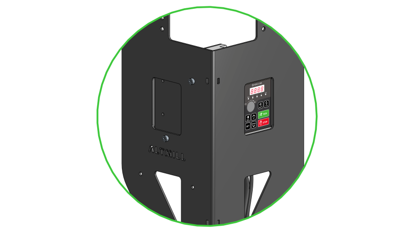
VFD unit correctly mounted, control panel accessible through leg cutout
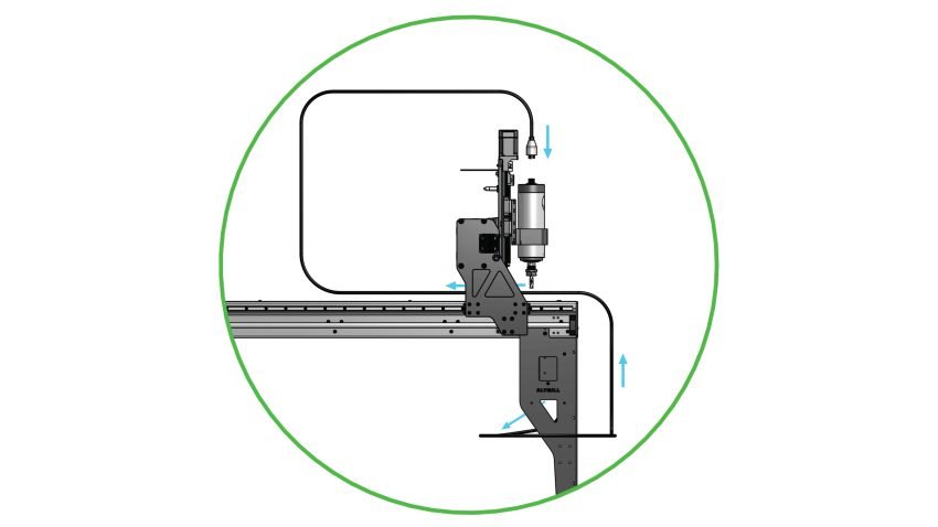
Grab the spindle cable from the bottom of the VFD unit, this will be the longest cable. Route this cable around the back of the table leg, wrapping around to the front side of the machine, then swing this cable over the top of the table, and under the X-axis rail. Leave this bundle of cable resting on a crossbeam for now.
It is important that this cable is routed in this path so that it can be run through the X and Y axis drag chains later on.
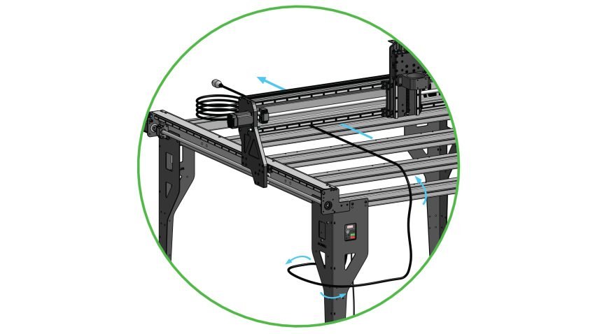
Initial spindle cable routing
Ensure the two screws which clamp the spindle mount are loosened fully, so that the spindle mount is fully open.
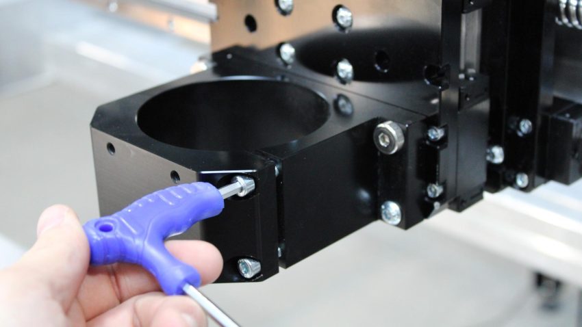
Loosening clamping screws on spindle mount
Grab the spindle and the foam packaging it came in. Place the spindle through the top of the spindle mount, and use the foam packaging to rest the end of the spindle over the front crossbeam.
Adjust the height of the spindle mount by turning the Z-axis ball screw, so that the end of the spindle sticks past the bottom of the mount by about 4.5”. This can also be adjusted later depending on your setup. Tighten the two clamping screws using the 4mm hex key to lock the spindle in place. Go back and forth between tightening both screws to ensure even clamping force.
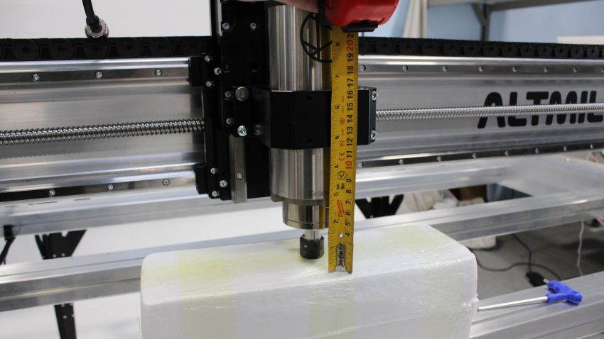
Spindle mount height adjustment
Grab the end of the spindle cable and bring it over the X-axis, guiding it to the top of the spindle. Match the orientation of the connectors before securely plugging the connectors together.
Side view showing complete cable routing path
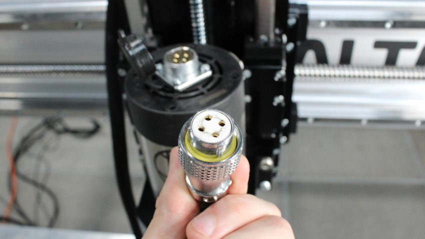
Pattern of connector holes on spindle cable plug
Fully secure the connectors by rotating the collar on the cable side clockwise, so that the collar is threaded onto the spindle connector. Pull the connector to check they are properly secured.
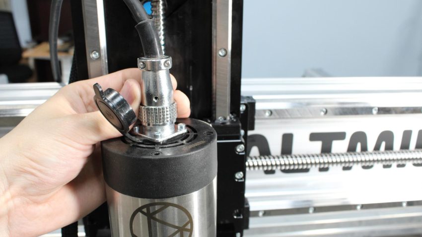
Spindle cable collar threaded onto spindle connector
Z-axis and X-axis Cable Routing
Plug in the Z-axis motor cables, and secure the power connector on this motor with a small flat screwdriver.
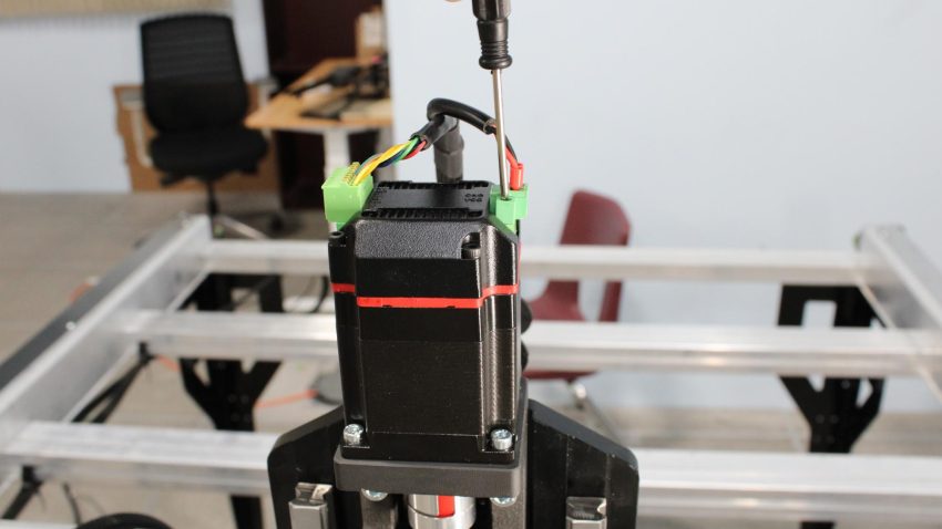
Fastening set screws on power connector at Z-axis
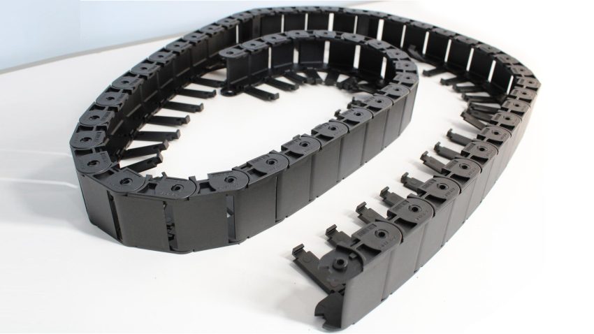
Both drag chain lengths come split into two halves for shipping. Grab all four halves, and join two halves together to create two equal full length drag chains.
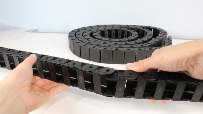
Connecting two ends of drag chains
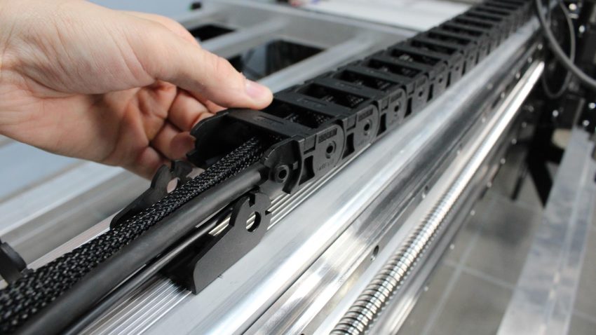
Use a small flat head screwdriver, pick, or another small tool to unlock the clips on both drag chains, by inserting the tool underneath the clip at the side with the screwdriver icon.
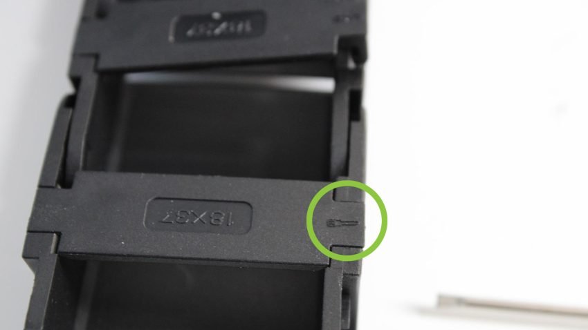
Drag chain clip with screwdriver icon indicated
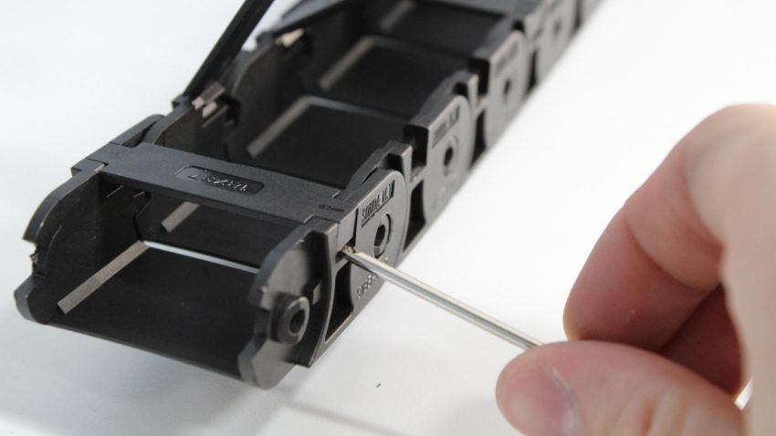
Prying open clip at the side with a small flathead screwdriver
All clips opened on drag chain
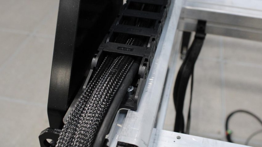
Unroll one drag chain, and lay this across the top of the X-axis rail. Make sure the drag chain end with the holes on the tabs is sitting on the right side of the machine. This end will attach on the top of the Z-axis at the drag chain bracket.
Drag chain laying on X-axis
Grab the bunch of cables (spindle cable, motor cable, inductive sensor cable) from the Z-axis, and begin running these inside this drag chain. They should enter through the right side of the chain, and exit from the left side.
Re-clip a few of the drag chain links as needed, to hold the cables in place while routing.
Routing cables through drag chain
Cables entering through right side and exiting through left side of machine
Once all the cables are routed through, finish re-clipping all links of the drag chain to fully lock the spindle, motor and sensor cables into place. Then attach the right end of the drag chain to the drag chain bracket on the rear of the Z-axis.
Attaching drag chain to the bracket on the Z-axis
Drag chain assembled onto the bracket
Attach the left side of the drag chain into the drag chain end that was previously installed on the top of the X-axis rail.
Drag chain attached to X rail
Remove the slack from any extra cables sticking out from the right side of the drag chain by gently pulling the cables out from the left side of the drag chain.
Pulling cables gently from the left side of drag chain
Make sure to leave a fair bit of slack in the spindle cable to allow the spindle to reach its lower travel limit without straining this cable.
Spindle cable with some slack to allow for Z travel
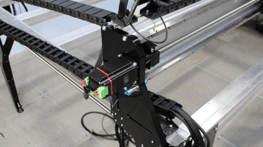
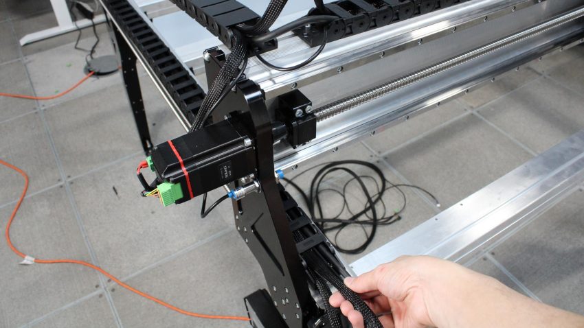
Grab the last motor cable, and install both green connectors into the X-axis motor. Lock in the power connector by screwing it into the motor with a small flat screwdriver
Installing motor connectors onto X-axis
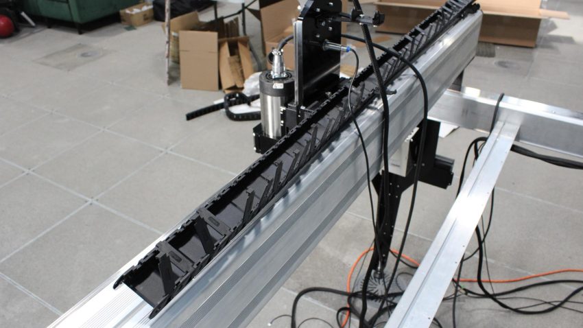
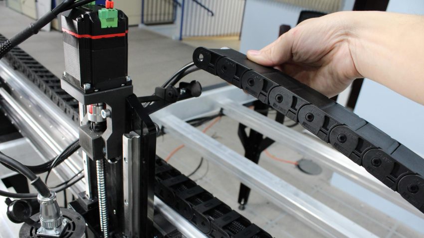
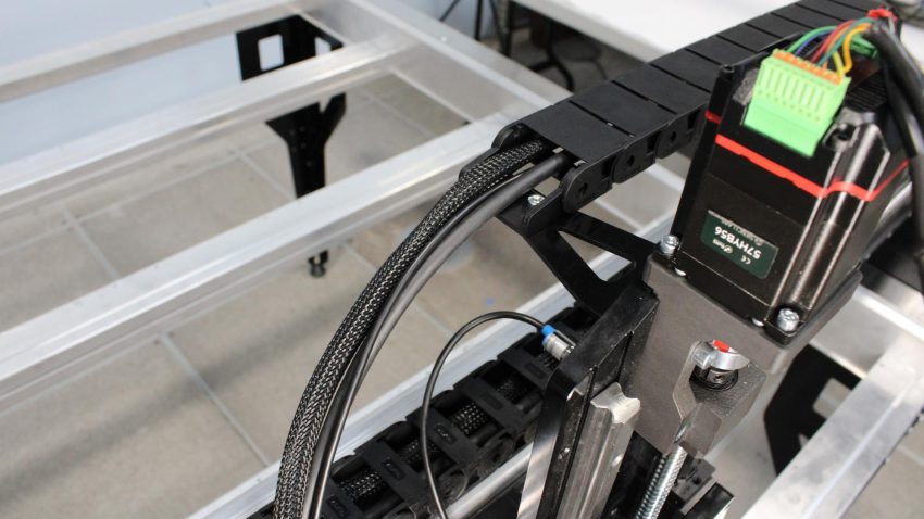
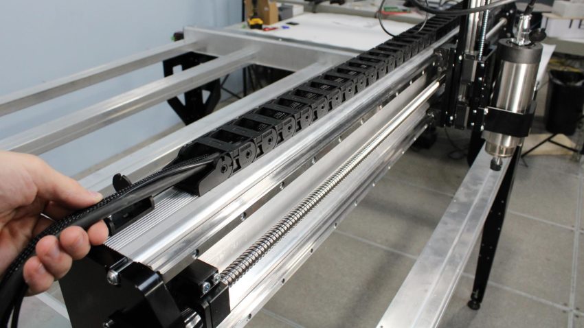
Lay the second full drag chain length across the left Y-axis rail, orienting it so that the drag chain end with holes on the tabs is at the rear of the machine. Take the bundle of wires coming from the drag chain, as well as the motor cable and inductive sensor cable mounted on the side of the X-axis.
Bundle of cables from drag chain, motor and inductive sensor
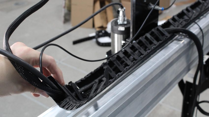
Grab the drag chain end from the rear, then run the bundle of five (5) cables through this end, then exiting near the front of the machine.
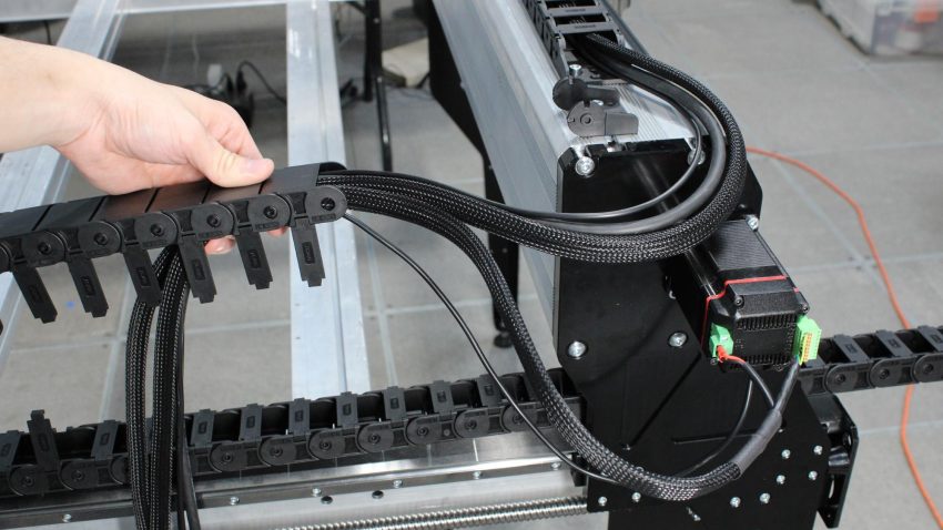
Routing cables, entering through drag chain end with holes on the tabs
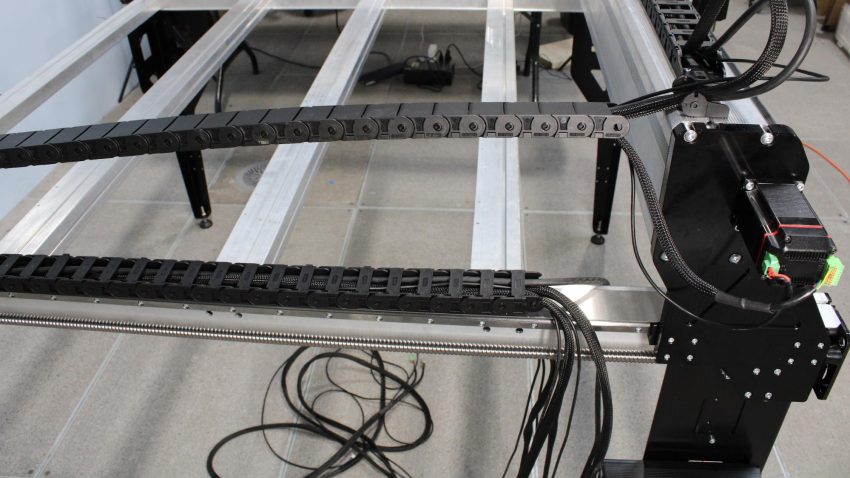
Cables exiting from the drag chain near the front of the machine
Connect the drag chain end with the holes on the tabs to the link mounted on the top of the X-axis rail.
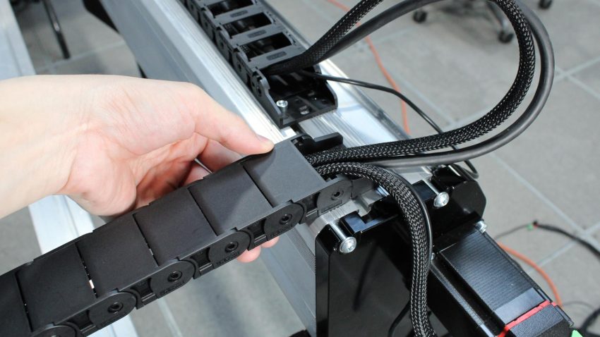
Connecting drag chain end to top of X rail
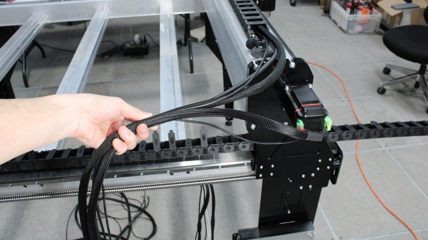
At the other end of the drag chain, gather all cables and guide them underneath the X-axis rail and over the left Y-axis rail, so they all exit out the front of the machine.
Drag chain end moved to front of machine, cables sit over the left Y rail
Attach the front end of this drag chain into the end link that was installed on the front of the Y-axis rail, then gently pull the bunch of cables to remove any excess cable slack where the two X and Y drag chains meet.
Attaching drag chain onto front of left Y rail
Gently pulling cables to remove slack
Take the bundle of 5 cables coming out the front of this drag chain, and secure these to the front left table leg using a small zip tie installed in the corner slot of the leg.
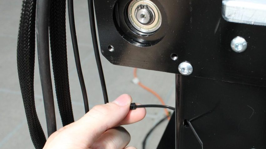
Looping zip tie into slot on front left leg
Securing bundle of cables with zip tie