
Parts List
- 1x Left Y Gantry Plate
- 1x Right Y Gantry Plate
- 1x X-Axis Assembly
- 6x Bump Stops
- M4-16mm Socket Head Cap Screws
- M5-16mm Socket Head Cap Screws
- M6-35mm Button Head Cap Screws
- M6 Washers
Bump Stop Installation
Install four (4) rubber bump stops onto each of the Y end plates using the M5-16mm socket head bolts, at each corner of the machine.
Bump stop installation on Y end plates
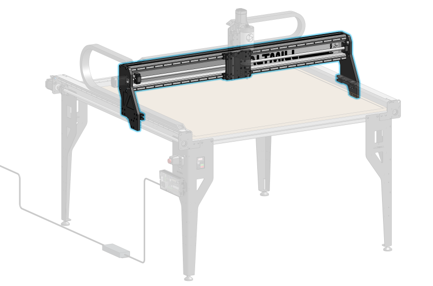
Y Gantry Plate Installation
Remove the clear plastic wrap surrounding the linear bearings and ball nut on the left and right Y-axis assemblies. Remove the plastic ball screw nut support packaging by sliding this out forwards or backwards.

Support packaging removal
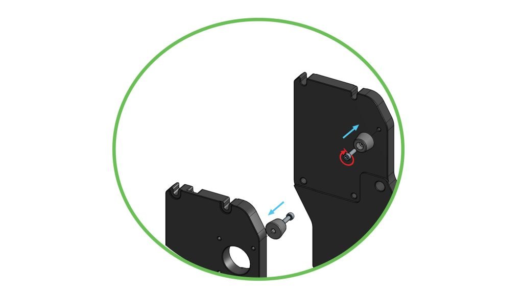
Take out the Y gantry plates, making note of the differences between the left and right plates. Specifically, the left Y gantry has holes which allow for the stepper motor to be mounted.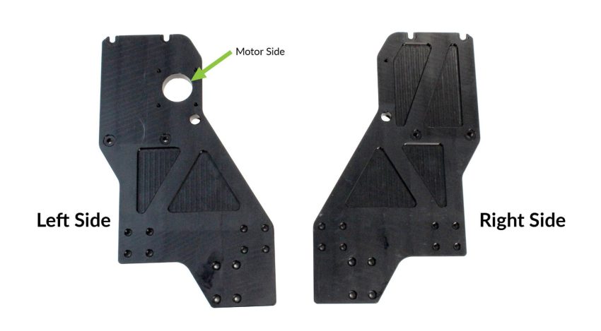
Left and right Y gantries
On each Y-axis gantry plate, there are two sets of four (4) holes in a square pattern, aligned in a row. These should match up with the two (2) linear guide blocks. With eight (8) M4-16mm socket head cap screws, first insert one screw through the Y-axis gantry plate into one of the linear guide blocks. Insert a second screw into the second block. Then, install the remaining screws into both blocks, but do not tighten at this stage.

Loosely fastening linear guide block screws
Slide the Y-axis gantry plate over top of the aluminum ball screw nut block. Install two (2) M5-16mm socket head cap screws diagonally, going through the plate into the aluminum block. If you received your AltMill after December 10th, install M5-20mm ‘ball nut screws’ included with your kit for these holes instead. Loosely secure.
Aligning Y gantry to aluminum ball screw nut block
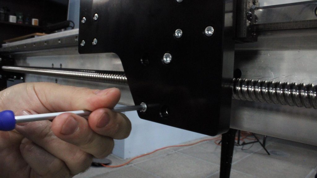
Loosely fastening aluminum block screws
Repeat the screw installation on the Y-axis gantry plate for the other side.
Push the left and right Y-axis gantry plates to the front bump stops.
You may now loosely install the remaining two screws connecting the gantry to the aluminum ball screw nut block on both sides.

Y gantry pushed against front bump stop
Install the remaining two (2) bump stops onto the Y-axis gantry plates using two M5-16mm socket head cap screws.
Installing bump stops onto Y gantries
X-Axis Assembly Installation
Grab the X-axis rail assembly and place it on the table. Orient the assembly so that the X gantry plate is facing upwards, and the notch on the plate is facing away from you.
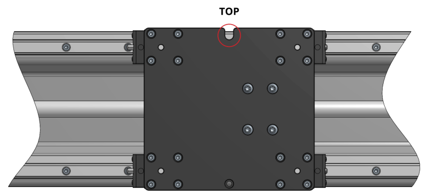
Top view of X rail assembly
Take four (4) M6 washers, then place them through four (4) M6-35mm button head cap screws. Insert two (2) of those prepared screws onto each end of the X-axis assembly, as shown in photos, having them stick out of the rail by about ¾” to 1”.
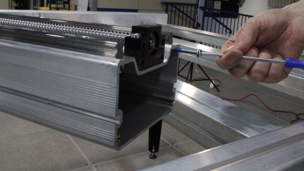
Installing washer and screw onto X rail, sticking out about 3/4″ to 1″
M6 hardware installed at two ends of X rail
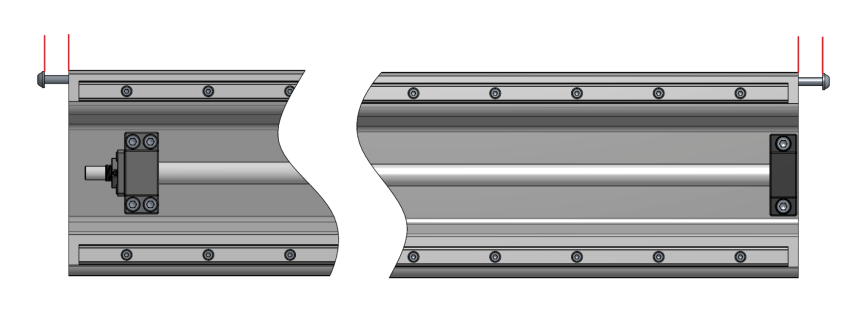
Lift the X-axis assembly, making sure the X gantry is facing towards you, then rotate the assembly so the bottom is slightly angled away from you. Mount the assembly onto the Y gantries by seating the front-facing screws on the rail end into the slots of the Y gantry, then seat the rear-facing screws into the second set of slots by pivoting the assembly towards you.
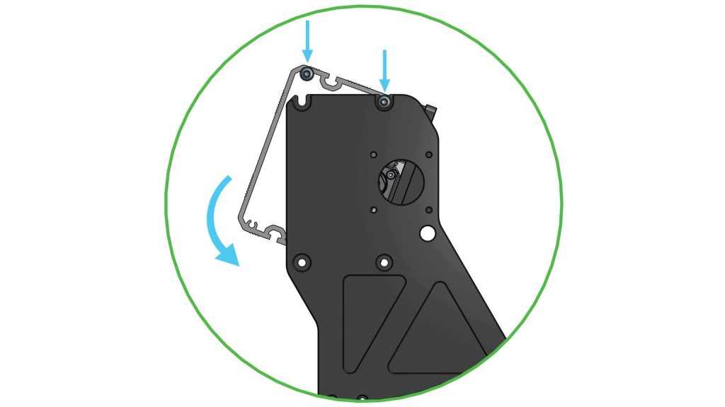
Left side view of Y gantry and X-axis assembly during mounting process
Mounting X-axis assembly onto Y gantries
Install the remaining M6-35mm button head cap screws into the two (2) lower holes on the X-axis assembly, no washers needed. Do not tighten the hardware.
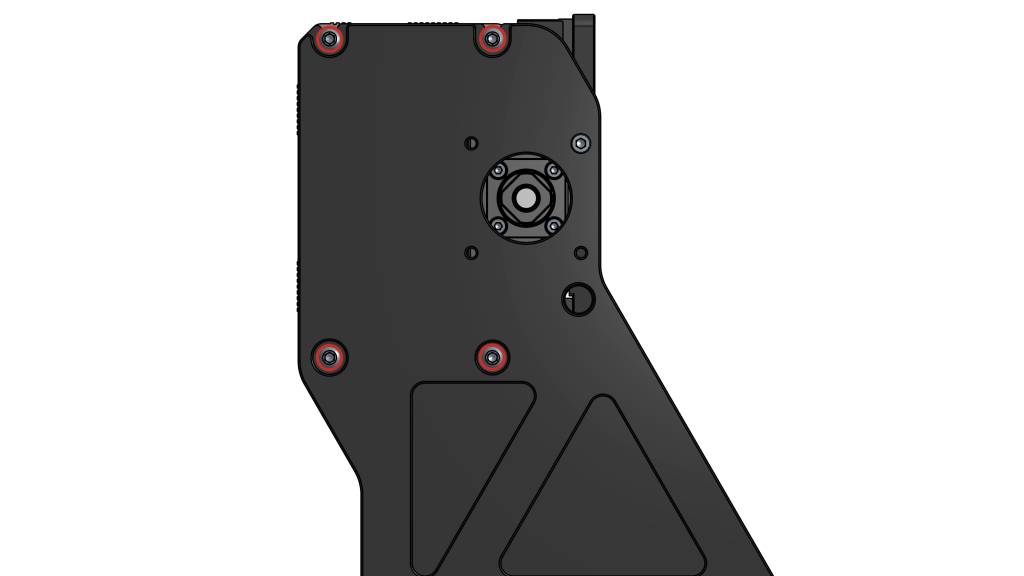 Loosely fastening X-axis assembly onto Y gantries
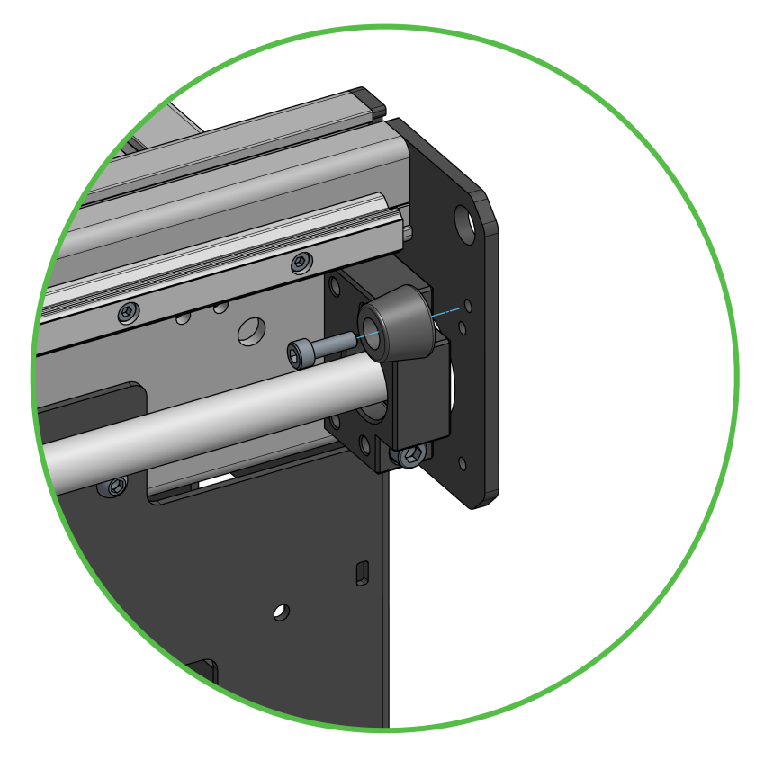
There is a recessed area on the Y-gantries that aligns the X rail to the correct position, squaring it to the machine. Use a clamp to push the X rail and left Y gantry into each other, so that the rail sits in the locating recess. You can now securely tighten the screws on the two ends of the rail, totalling to eight (8) screws. Leave the clamp on until the end of this assembly section.
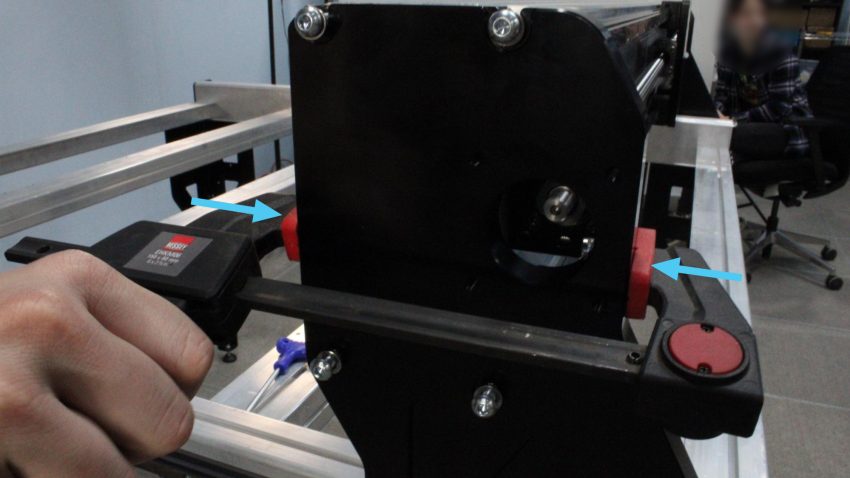
Clamping X rail and Y gantry for alignment before securely fastening screws
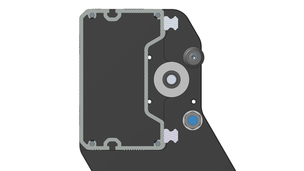
Cross section showing locating recess on Y gantry
Tighten all the screws for the Y gantry, at the linear guide blocks and aluminum ball screw nut block, totalling to 24 screws.

Fastening screws connecting X rail to Y gantry
Remove clamp. You have now completed the X and Y gantry assembly, great work! You deserve a small break with a beverage of your choice.