
Closed vs Open Loop Stepper Motors
Closed loop stepper motors offer many advantages over a regular open loop stepper motor. An open loop stepper motor is the most common, inexpensive type of stepper motor. These are typically found in 3D (and 2D!) printers, CNC machines (such as the LongMill), and some robotics applications.
With open loop motors, a command is sent to the motor driver, and the motor driver tells the motor to move some amount. Whether or not the motor actually moves that exact amount is unknown to the rest of the system. If there is some sort of resistance, disturbance, or obstacle in the way that prevents the motor from spinning its intended amount, the motor will ‘skip steps’ and we’ll essentially lose track of where we think the motor is.
With closed loop motors, a command is sent to the motor driver, and the motor driver tells the motor to move some amount, while simultaneously monitoring the position of the motor using a sensor. If the motor position is lagging behind where it is expected to be, the motor will receive more power to ensure that the motor gets to the specified position without any skipping. In the case where the motor is somehow obstructed from spinning entirely, it will enter an ‘Alarm’ state and shut off power to prevent any damage. The motor driver will communicate back to the machine controller to let it know that something has gone wrong, and the controller can halt the entire system to prevent any sort of damage.
Asides from no potential for loss of position, there are a few other benefits of closed loop stepper motors:
- More efficient operation when idle since extra power is only used if some torque is applied to the motor’s shaft and the motor must react to maintain its position
- More efficient operation overall, since the motor will only use as much power is needed to move
- Less heat buildup in the motor since idle and operational efficiency is improved
- Less noisy
- Faster maximum running speeds
AltMill Closed Loop Stepper Motors
The closed loop stepper motors used on the AltMill’s X and Y axes are rated for 2 NM of torque, while the motor on the Z-axis is rated for 1.2 NM of torque. Each motor is tested individually in-house.
Microstepping
The closed loop stepper motors which are used on the AltMill function by receiving a certain number of ‘step’ pulses from the controller which ultimately determines how much and how fast the motor the spin. ‘Microstepping’ is a setting/configuration which will ultimately determine how much the motor spins for a given number of pulses or ‘steps’ sent to the motor.
By default the X and Y axis motors are set to use 1/16 microstepping, while the Z-axis motor uses 1/4 microstepping, which can be adjusted by changing the various small DIP switches on the rear of the motor. Do not adjust these switches if you’re not sure what microstepping is, or if you do not have a reason to change them. The first switch #1 is only used to invert the direction of the motor if needed. The table below shows the various switch positions for a given microstepping value:
| Microstepping | Switch #2 | Switch #3 | Switch #4 | Switch #5 |
| 1/2 | ON | ON | ON | ON |
| 1/4 | OFF | ON | ON | ON |
| 1/8 | ON | OFF | ON | ON |
| 1/16 | OFF | OFF | ON | ON |
| 1/32 | ON | ON | OFF | ON |
| 1/64 | OFF | ON | OFF | ON |
| 1/128 | ON | OFF | OFF | ON |
| 1/256 | OFF | OFF | OFF | ON |
If you happen to run your machine into itself or an obstacle, causing a motor to enter an ‘Alarm’ state, an emergency stop alarm will be triggered at the controller and the motor that has been alarmed will be unpowered, allowing you to spin it freely. You’ll also see a small flashing red light near the power connector at the motor, where a green light is also illuminated. To help identify the problematic motor, you can also open the ‘console’ in gSender and check which motor is in an alarm state.
Connections
Each AltMill motor has two separate connectors – one for power, and one for signal. The pinout for both of these connectors is shown in the diagram below.
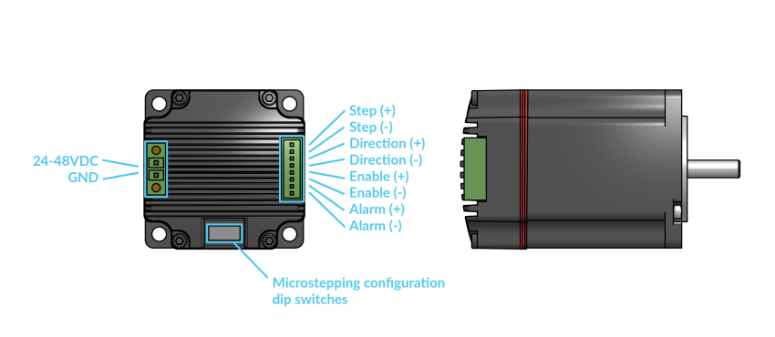
The power connector uses a 2-pin 3.81mm pitch Pluggable Terminal Block connector with two locking screws. DC power can be supplied to the motor within the range of 24V to 48V.
The signal connector uses an 8-pin 2.5mm pitch pluggable terminal block connector. This connector uses spring terminals – to install or release a wire from the connector, simply use a small screwdriver to press down onto the orange contact to disengage the spring which holds the wire.
Signals are sent to the motor using what are known as differential pairs. This means each type of signal input or output uses two equal signals of opposite polarity, allowing them to be much more reliable against outside interferences.
Motor Specifications
Specifications of our closed loop motors can be found in this article on our AltMill resources page.