
Parts List:
- Laser diode extension cable (2.5m, blue)
- Laser cooling fan extension cable (2.5m, red)
- Air assist extension cable (2.5m, yellow)
- PWM signal extension cable (0.6m, purple)
- LaserBeam driver
If you have the AltMill you will need a longer set of extension cables, which will be released soon. In the meantime you can run the existing cables outside of the drag chain, fastened with zip ties.
If you wish to route the laser cables through the LongMill drag chain, you will need to unclip all the drag chain links.
Unclipping drag chain links using flat head screwdriver
Route the blue, red and yellow cables through the entire drag chain, making sure the cables are able to reach the connectors at the laser.
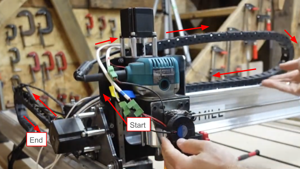
Front view of cable routing path
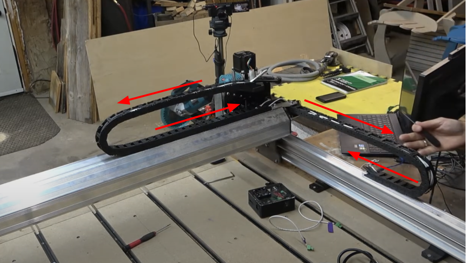
Back view of cable routing path
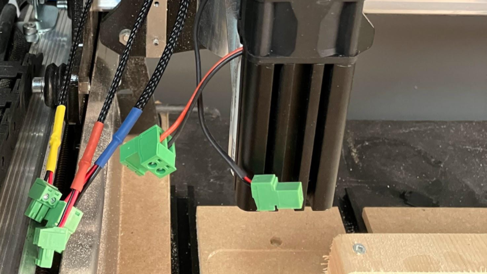
Blue, red and yellow cable connectors next to laser diode assembly
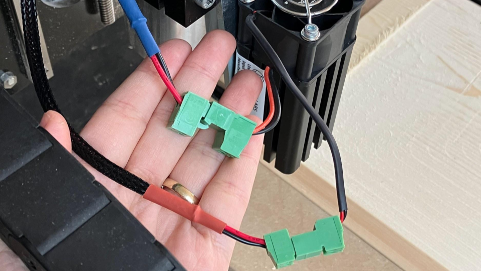
For each connection, make sure that the red wire from the female side meets with the red wire from the male side. Attach the fan connector to the red cable. Attach the diode connector to the blue cable. Make sure not to mix the diode and fan connections!
Red and blue cables connected to cooling fan and diode respectively
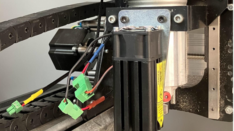
Cooling fan and diode connections
Once you are sure the cables are properly positioned and attached, close your drag chain tabs.
The following instructions will detail cable connections to the laser driver and/or CNC control board, whether you have the SLB/SLB-EXT or the LongBoard.
Laser diode → Driver
The laser diode will receive power through the driver. Assuming one end of the blue cable is already plugged into the diode, connect the blue cable to the driver. Make sure that the location of the driver connection is correct as shown.
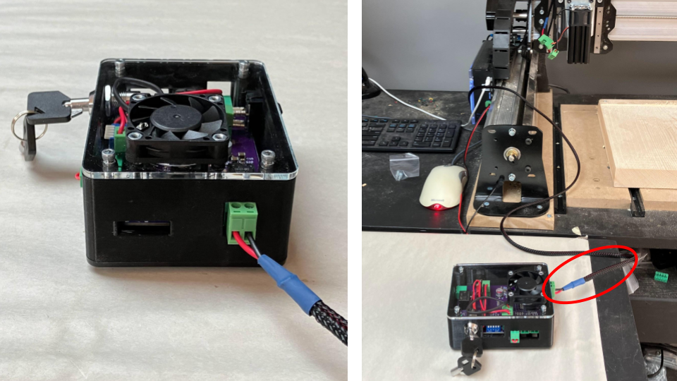
Laser diode to driver connection
Cooling Fan → Driver
The cooling fan will also receive power through the driver. Assuming one end of the red cable is already plugged to the fan, connect the red cable to the driver. Make sure that the location of the driver connection is correct as shown.
Cooling fan to laser driver connection
Air Assist → Driver (Optional)
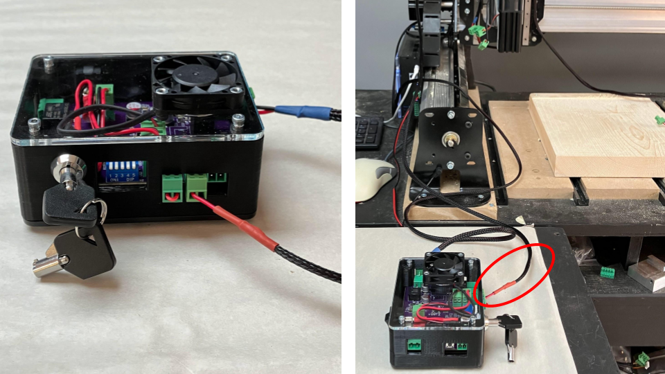
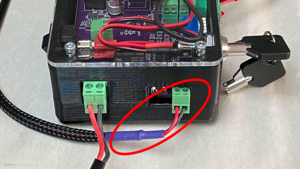
To simplify your building process, we will leave the air assist assembly off the diode. However, we can plug one end of the yellow cable into the driver, leaving the other end free, in case you need to use air assist in the future. Make sure that the location of the driver connection is correct as shown.
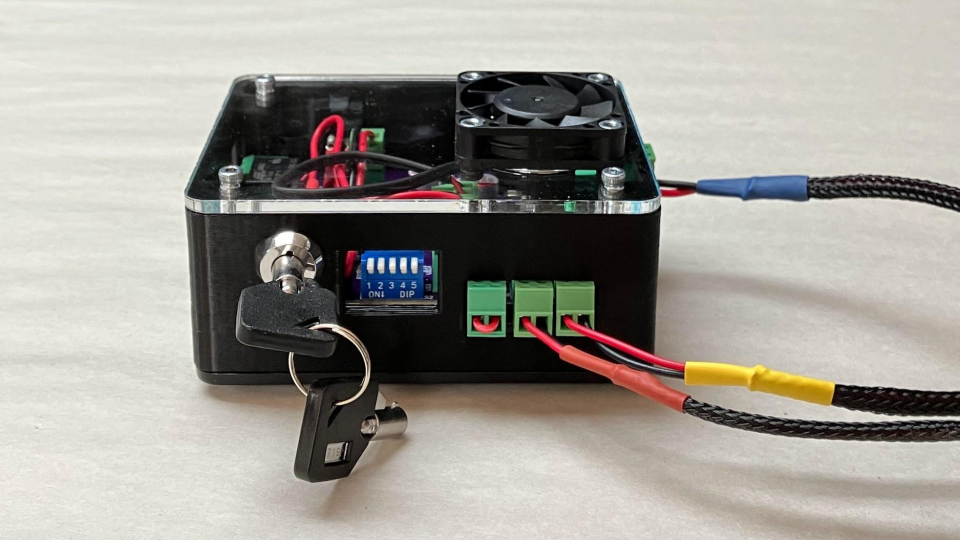
Air assist to laser driver connection
Driver → Controller
This connection allows you to control your laser through the CNC controller. The driver uses this PWM signal to turn on/off the laser, as well as adjust the intensity and frequency.
On one end, plug in the male connector to the driver’s PWM signal input, at the location shown in the photo.
Connecting PWM signal input to driver
The following steps will vary whether you have the Longboard or the SLB. Please read carefully to ensure you complete the proper steps for your controller.
For the Longboard, plug in one end of the purple cable to the controller, making sure the red wire is seated at the “SpinPWM” and the black wire is seated at “GND.”
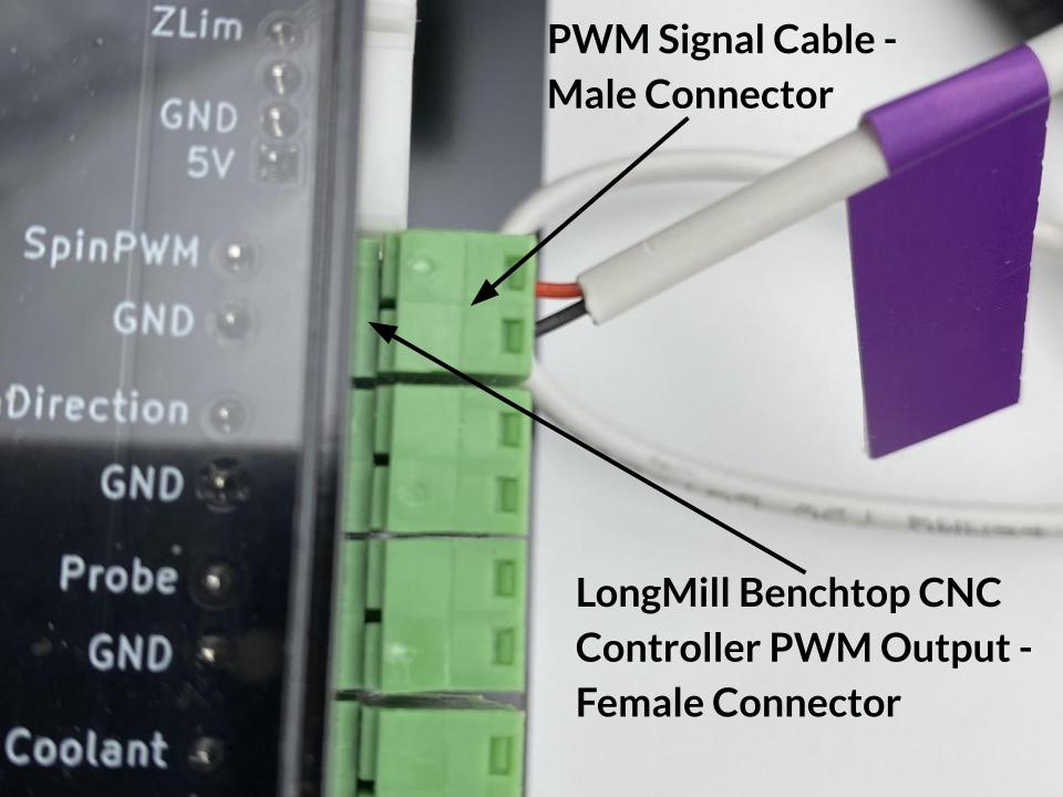
Connecting PWM signal input to Longboard
If your controller is an SLB or SLB-EXT, you will plug in the cable at the “LASER” port. Ensure that the red wire cable is seated at the “PW” port and the black wire is seated at the “GD” port.
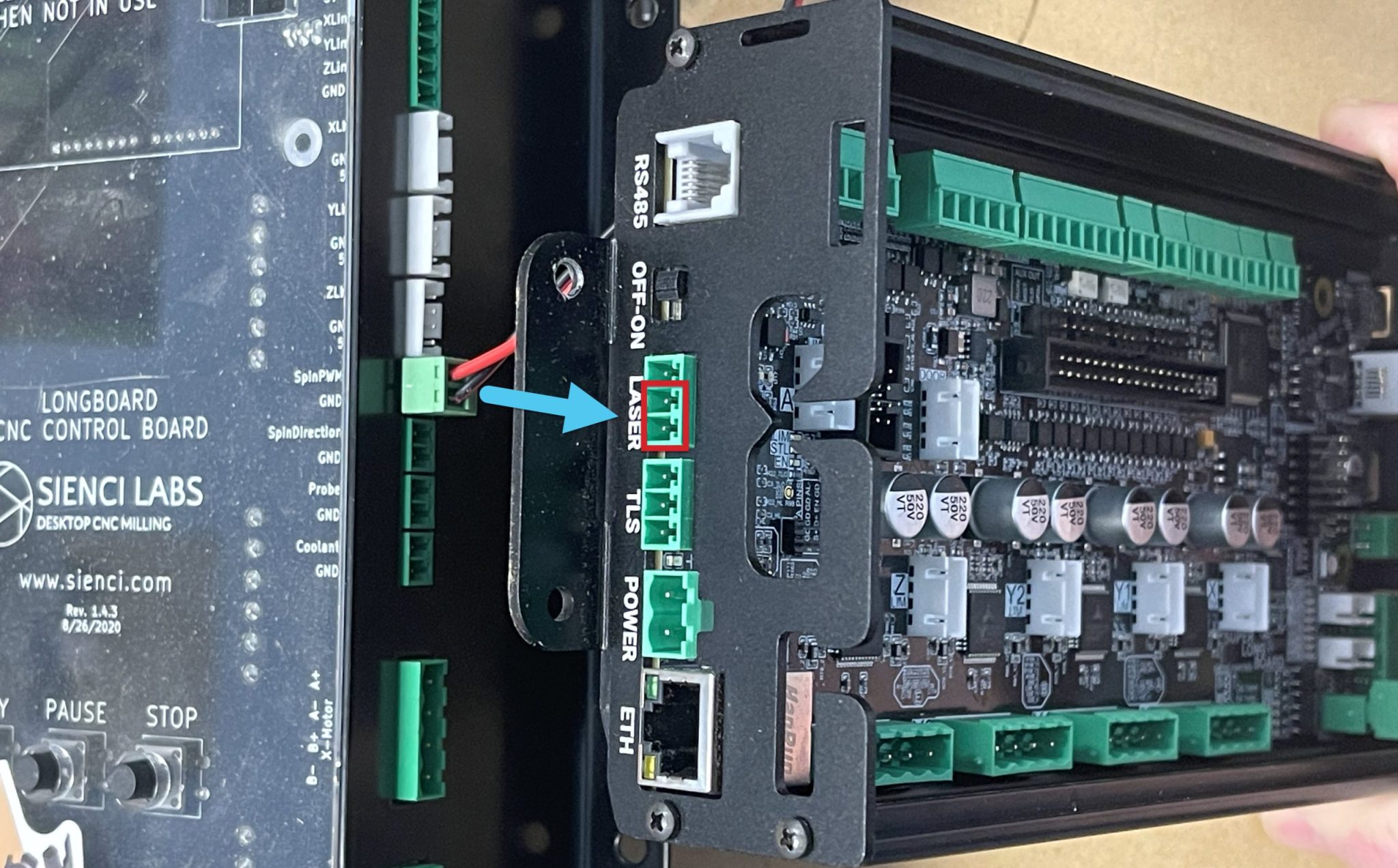
Side view of SLB with LASER port indicated
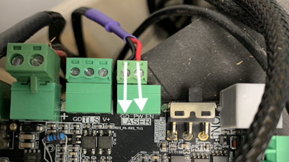
Front view of SLB with PWM signal connector inserted