What are Offsets? 🎯
Offsets are the adjustments of a CNC machine’s coordinates to account for the different dimensions and positions of any tools you may be using. In the case of the LongMill, users may seek to use the LaserBeam add-on right after completing an ordinary milling job. To ensure proper alignment of the LaserBeam to the workpiece, without having to go through a tedious manual setup, offsets can be utilized, allowing for a seamless transition from router/spindle to laser use. For such purposes, gSender has been equipped with an offset function. To utilize it, users simply enter a set of x and y coordinates, then follow a straightforward process to achieve their desired alignment results. It is a much quicker process than manually realigning the LaserBeam to the workpiece in order to set a new origin point. This resource page explains the entire process in detail.
The most accurate method for finding your offset coordinates involves using our open-source CAD models to measure the distance between the LaserBeam and router/spindle center points, in both the x and y dimensions. The coordinates can also be found through a simple process of trial and error. Both methods for finding these values are outlined in detail below on this page.
This resource page provides all the necessary offset coordinates one would need to utilize the gSender feature for their own projects. Below are tables containing all the theoretical coordinates that would work to realign the LaserBeam with the use of the offset feature. Notice, however, the use of the word “theoretical”. Unfortunately, due to manufacturing processes, there will be variations in the dimensions of different LongMill parts our users own. While these imperfections may be small, they can compound. Coordinates given in the provided table may not work for your specific setup, may work perfectly, or may have very minimal levels of error. Due to this, an additional guide containing the steps on how to manually determine your specific offset coordinates, without the use of CAD software, is available on this page.
Different Mount Types for Offsetting 🔧
The first thing you want to do is identify the specific laser and router mount models that you own. Router mounts vary according to your LongMill model.
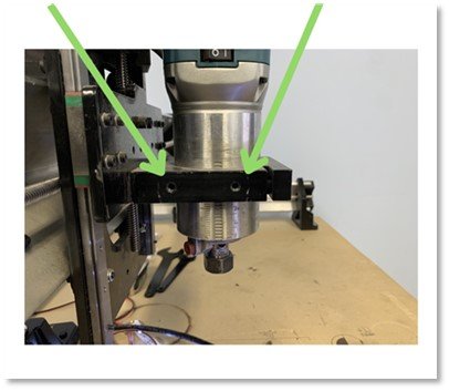
- Models MK1V1 – V4 (Mark 1 version 1 to 4) router mounts possess holes for mounting on their side
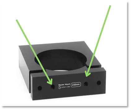
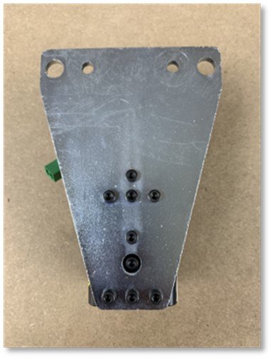
- Models MK1V4B – MK2 (Mark 1 Version 4B to Mark 2) possess mounting holes on their front face:
-
- Mounting Hole Location for MK1V4B-V2
-
- Mounting Hole Location for MK1V1-V4
Both router mount types come in different sizes. This variation in dimensions affects offset values, thus it is important to identify the specific router mount that your LongMill currently uses.
- MK1V1-V4 router mounts come in four different sizes: 52mm, 65mm,71mm, and 80mm.
- MK1V4B – MK2 router mounts come in three different sizes: 65mm, 71mm, and 80mm.
For both router mount types, the associated dimension can be located on the front face:
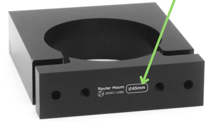
Router Size Labelling
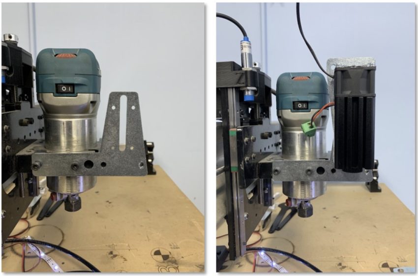
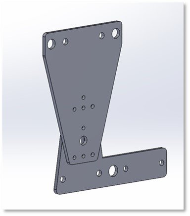
Offset values will also be affected by the specific mount used to attach your LaserBeam add-on. There are two options for LaserBeam mounting, those being the LaserBeam Vortex Riser Mount shown at the beginning of this page, and the standard mount that comes with a purchase of the LaserBeam attachment, which is shown below:
Standard Mount
LaserBeam Vortex Riser Mounting Variations 🌀
Things vary a bit when examining the Vortex Mount. Offset values will change depending on how you choose to attach the Vortex to the router mount. The following figures show different ways in which to attach the Vortex in correspondence to the router mount types (MK1V1-V4 and MK1V4B – MK2). Each attachment setup has been given a name to make them easier for you to reference later:
MK1V1-V4:
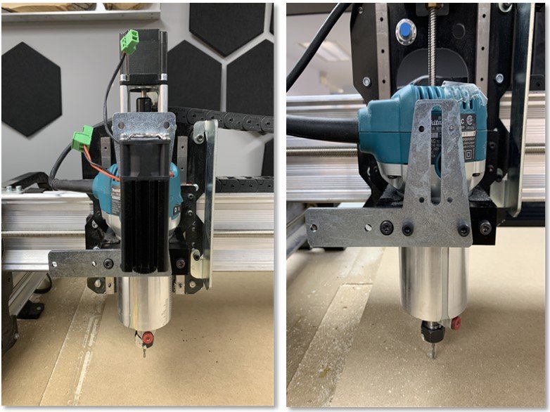
Orientation A
Orientation B
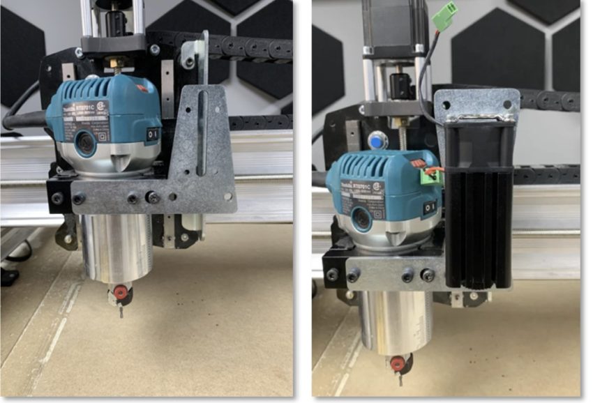
MK1V4B- MK2:
Orientation C
*Note: Orientations A and B could both be utilized in an inverse manner by simply flipping the bracket. You would have to note the direction of each coordinate (is it negative or positive in reference to the position I want to achieve?), but the actual values do not change. More on determining coordinate directions is discussed further below.
With a base understanding of the different components that play a role in determining these values, we can now discuss how to actually utilize offsets in your project. To do this, there are two main methods that we will review:
- Offset Tables
- Trial and Error Offsetting
Offset Tables 📑
The following tables contain the offset values in correspondence to mount type, model, and orientation. This method involves using the values from these tables, so refer back to this section when actually attempting to follow the upcoming process:
Standard Laser Mount W/ MK1 V1-V4
| Router Mount Size | X-coordinate | Y-Coordinate |
| 52 mm, 65 mm, 71 mm | 68.829 mm | 9.4 mm |
| 80 mm | 73.829 mm | 9.4 mm |
Standard Laser Mount W/ MK1 V4B-MK2
| Router Mount Size | X-coordinate | Y-Coordinate |
| 65mm | No Offset Needed | 66.42mm |
| 71mm | No Offset Needed | 69.98 mm |
| 80mm | No Offset Needed | 72.65 mm |
Vortex Laser Mount W/ MK1 V1-V4
| Orientation | Router Mount | X-coordinate | Y-Coordinate |
| B1 | 52 mm, 65 mm, 71 mm | 72.26 mm | 60.1 mm |
| B1 | 80 mm | 77.26mm | 60.1 mm |
Vortex Laser Mount W/ MK1 V4B-V2
| Orientation | Router Mount | X-coordinate | Y-Coordinate |
| A1 | 65mm | No Offset Needed | 69.85 mm |
| A1 | 71mm | No Offset Needed | 73.41 mm |
| A1 | 80mm | No Offset Needed | 76.08mm |
| A2 | 65mm | 69.50623998mm | 69.85 mm |
| A2 | 71mm | 69.50623998 mm | 73.41 mm |
| A2 | 80 mm | 69.50623998 mm | 76.08 mm |
Offset Process 📝
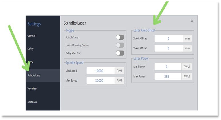
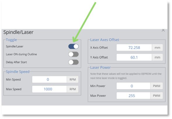
- Before even beginning your initial milling job, set the origin for your workpiece using your router/spindle. After doing this, on the gSender application, hit the settings button (is a gear) on the top far right. Click on the Spindle/Laser section, and on the right, you should be able to locate the “Laser Axes Offset” tabs. There will be two tabs, one for the x-coordinate and one for the y-coordinate of the given offset:
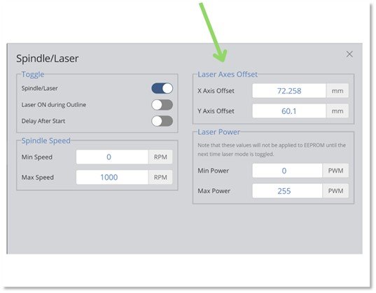
- Refer to the offset tables, taking note of your specific mount types, and if applicable, mounting orientation. From here, grab your needed x and y coordinates from the relevant table, and input them into the “Laser Axes Offset” tabs. Note: Remember, all table dimensions are in millimeters.
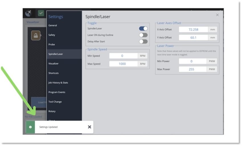
- Ensure to press enter on your keyboard after inputting the values so they save. If you do this correctly, a bar with the phrase “ Settings Updated” will appear at the bottom left of your screen to indicate this:
*Note: Depending on your setup, specific coordinate values may be negative or positive. You’ll have to determine which directions would logically allow for proper alignment and input them accordingly. This can be a bit confusing at first, so if you are unsure about how to do this, refer to the section below, titled “Understanding Directions” .This is very important to ensure you complete the process properly.
- Exit the settings and return to the gSender visualizer. Now, adjust the z-position of your router/spindle. This adjustment will depend on the orientation of your router/spindle to your laser, and may require you to move up or down in the z-direction. However, ensure that you raise the router/spindle high enough away from your workpiece to avoid unwanted scraping or cutting of the project when the offsets are applied, and the router/spindle begins to be moved. Also ensure it is high enough to avoid crashing your LaserBeam as well as mount. You may also want to adjust the height with your LaserBeam focus finder for optimal use:
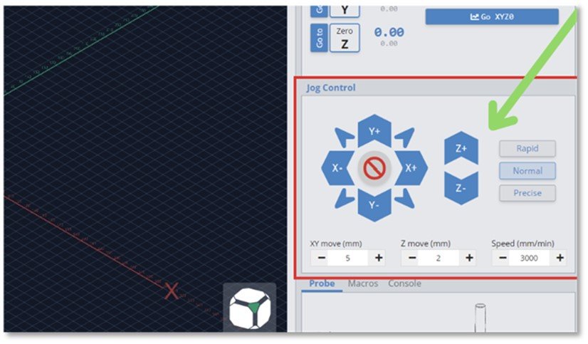
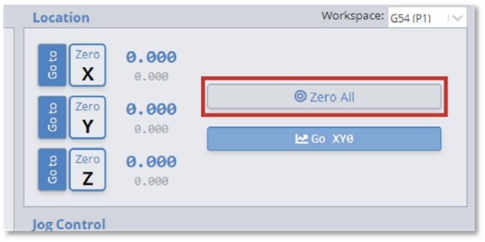
- After adjusting the spindle on the z-axis, you now want to hit the “Zero all button”once more to set your origin:
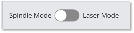
- Now you want to return to the settings tab. Click on the Spindle/Laser section, and under the “Toggle” tab, enable “Spindle/Laser”:
- Now proceed to switch from spindle mode into laser mode:
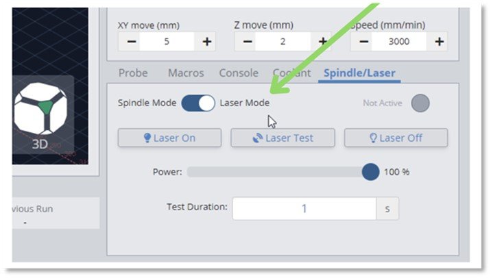
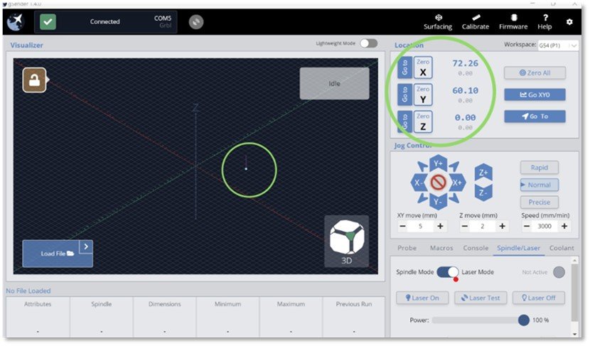
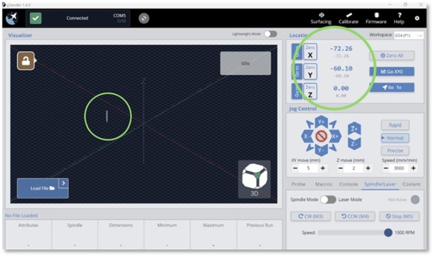
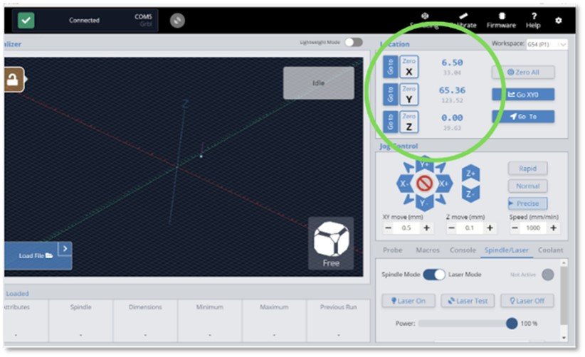
- You will now note that your x-coordinate and y-coordinate will display as your inputted offset values, and your visualizer will show the laser offset to this position. Make sure that this is the case:
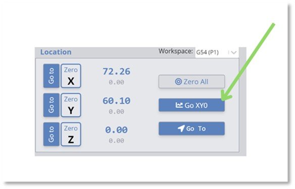
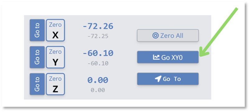
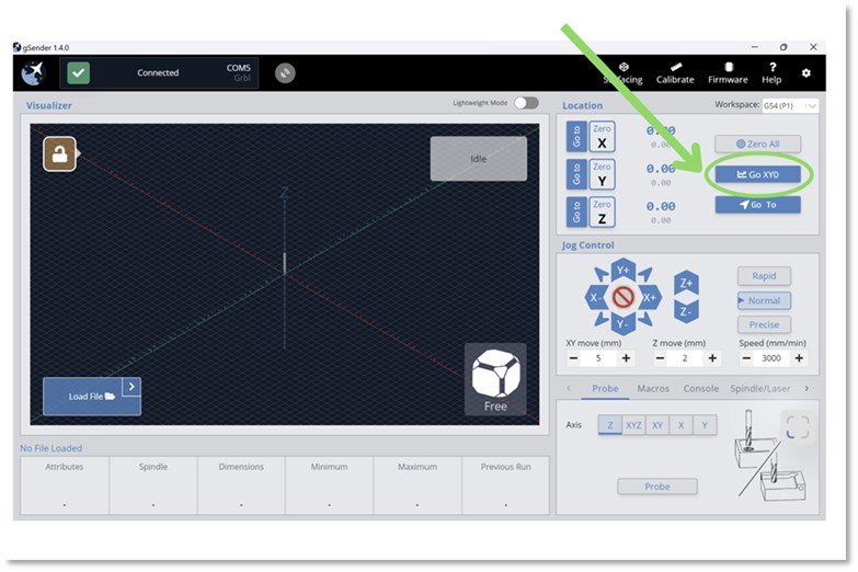
- At this point, we now want to hit the “Go to zero” button. This will move your LaserBeam and nearly perfectly align it with your workpiece’s set origin point, in turn completing the process.
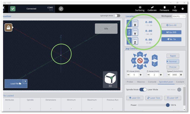
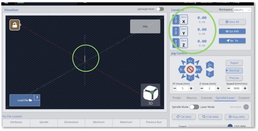
- On the Visualizer, your laser will now appear at the origin point, and your coordinates will now all be zero:
- Assuming you want to return to router/spindle use, switch back into spindle mode:
- Your router/spindle will now appear offset, and the coordinates will have the same value as the offsets entered, but in the opposite direction:
- Once again, hit the “Go to zero” button.
- Your spindle will now be nearly perfectly aligned with the original origin point. It once again will also display as such on your visualizer.
- At this point, you can continuously swap between laser and router/spindle use by switching between modes and hitting the “Go to zero button”. As noted before, there is a chance that these specific coordinate values may not work for your given setup. If this turns out to be the case and your alignment is visibly off, refer to the section titled “Trial and Error Offsetting”.
Understanding Directions ➡️
It is important to figure out the proper direction of your offset values before entering them into gSender. This can be a bit confusing at first. Take your time reading and examining the photos and this process will become easier.
- Ensure that you have already set the origin point for your workpiece using your router/spindle, or at least know where you intend to set your origin point. After this is done, look at the orientation of your origin point and laser in comparison to your gSender jog controller.
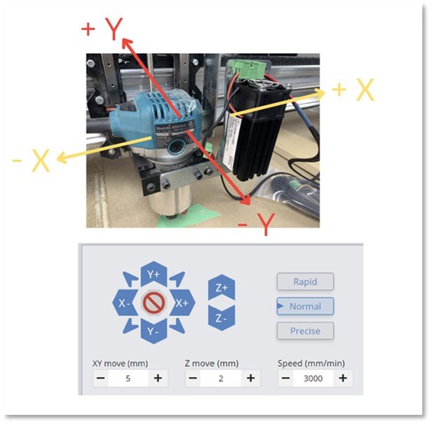
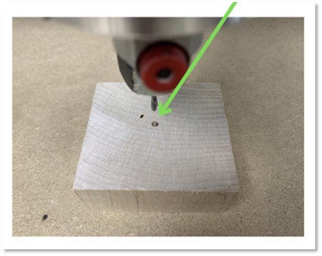
- Take note of which way your LongMill would logically have to move for your laser beam to align with your set origin. Remember, the whole purpose of utilizing offsets is to move your LaserBeam’s center to the set origin of your work piece, which is the location of the router/spindle’s centerpoint. Let’s look at an example with a router mount of orientation A . We only need a y-offset for this orientation, but we must take note of what sign the coordinate should have:
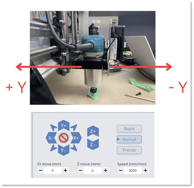
- In the photo above, we see that the router/spindle is directly above the green tape, at the point in which we have set the origin, but the laser needs to be moved in the +Y direction to be centered.
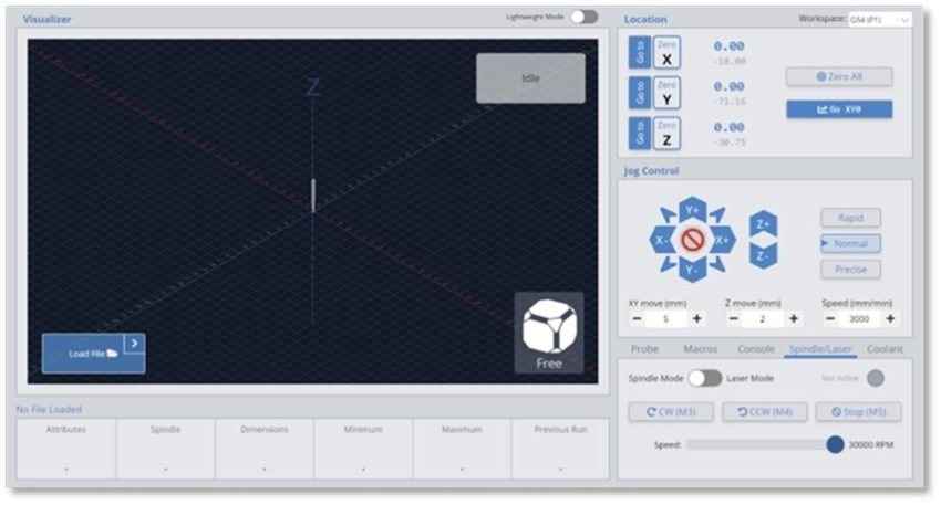
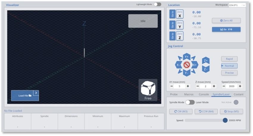
- Thus, you might think of entering your offset value as a positive number. However, this isn’t correct. You would actually want your offset value to be negative. To illustrate this, let’s look at how the visualizer would display the router/spindle and laser during this process. Before you do anything, assuming you have already set your workpiece origin, your router/spindle will be displayed on the origin point of the visualizer as shown below:
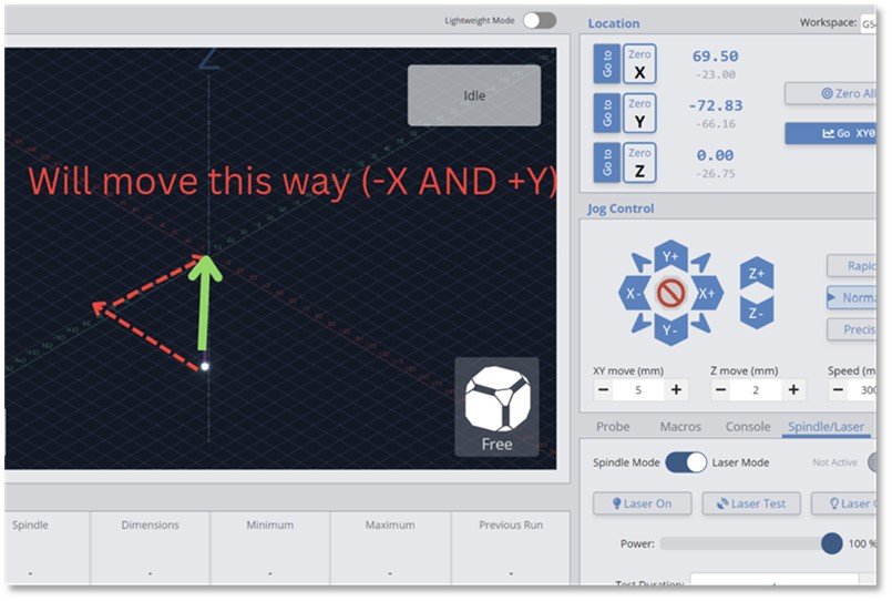
- Now, after we enter our offset values, if we switch over to laser mode, we can expect the visualizer to display the beam offset from the origin by the coordinate values inputted, again, as shown below. When we hit “Go to Zero” , it will align with the origin by moving in the +y direction, which is what we want:
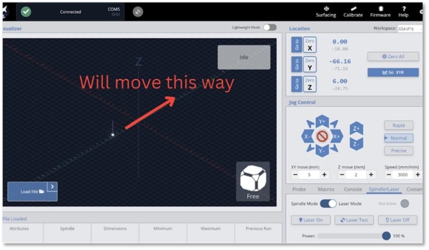
- The reason we used a negative y-coordinate is because, as seen above, by inputting the offset, the software believes that the Laser beam is 66.16 mm away from the origin point in the -y direction, and will thus move it 66.16 mm in the +y direction to align the laser to the origin point.
- To simplify this, when you determine which direction your laser will have to be moved in for alignment, in this case, the +y direction, the offset coordinates will have to have the opposite sign of the direction in which you intend to move. Now we can put this together and go through an example involving both the x and y coordinates.
- This time we are working with orientation B. Once again, let’s start by mapping out how our physical setup corresponds to our jog controller. Set the origin point for your workpiece using your router/spindle. Based on your setup, see which direction in which the laser will have to be moved to reach the router/spindle’s current position. Match that to the jog control coordinate system.
- Based on our setup, we would want our machine to move the laser in the +y and -x direction for proper alignment.
- With this now in mind, based on our rules established above, to achieve this result, we should make our x coordinate positive and our y coordinate negative.
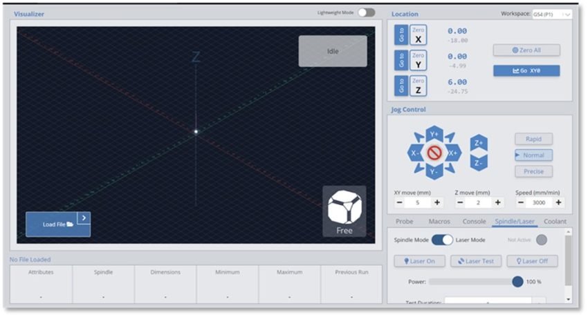
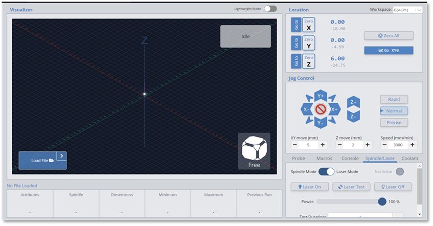
- Once again, at this point, our router/spindle is displayed at the origin on the visualizer:
- We now switch into laser mode and see our offset has taken effect. Our x has been offset in the positive direction and our y has been offset in the negative direction. Thus, our laser will be moved in the -x direction and +y direction, which again, is what we want.
- It is now properly aligned with the origin
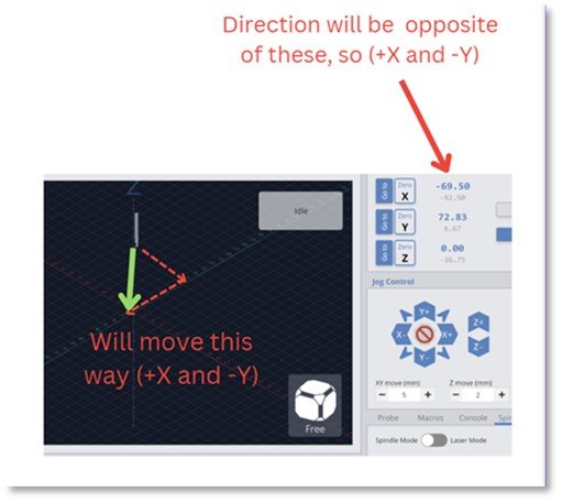
- When you return to spindle mode, it is key to note what direction in which your router/spindle will have to move to return to the origin. This is relatively simple, as it will move in the exact opposite direction in which your laser was moved during the offsetting process. In the case of our above example using orientation B, our router/spindle would move in the +x direction and -y direction to return to zero. You can also remember this by noting it will move in the opposite direction of the newly displayed coordinates in the location tab:
Trial and Error Offsetting ❎
In scenarios in which the offset table values are not compatible with your specific setup, you can simply use a method of trial and error to achieve similar results.
- Begin by marking an indent into a scrap piece of material with your router/spindle. After making this indent, adjust your z-position and raise your spindle until it is a reasonable distance away from your scrap piece of material. Do not tamper with the x and y coordinates while doing this. After you have raised the spindle to a reasonable height, hit the “Zero all” button. You have now set this specific indent point as your origin. This is important for later on:
Initial Indent
- Proceed to move into laser mode. At this point, you want to manually move your LongMill with the jog control to align the LaserBeam’s centerpoint with that of the indent’s. As you move around, occasionally fire the laser at low power to see exactly where the centerpoint lies. You’ll want to focus the beam to a similar size as that of the indent. Continue firing and adjusting the LaserBeam’s position until it eventually aligns with the indent:
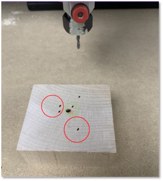
Alignment Attempts
- After you have done this look at the location tab and take note of the coordinates displayed. These coordinates will now act as your offset values, as they are the distance in which the LaserBeam must be moved to align it with the origin point.
- Now, with these values, you can follow the exact process outlined in the “Offset Tables” section. Begin by returning to spindle mode. Then hit “Go to zero” to return to the origin point.
- Open the settings and go to the Spindle/Laser section to enter the offset values you acquired through the trial and error firing process. Remember to ensure you apply the right directions to each coordinate. Save these values, and return to the visualizer. After this, enter into laser mode and hit the “Go to zero” button for proper alignment.
The actual process of using the offset coordinates is the exact same between the two methods discussed on this page. The only difference is in how one acquires those values.
In conclusion, all the information given above tells you all there is to know about offsets, including how to use them and why you should utilize them to take your projects and efficiency to the next level.
Bonus Section** 🌟
Finding Offsets 📏
Utilized offset values are nothing more than the distance between your router/spindle’s centerpoint, and the centerpoint of your LaserBeam. For those interested in how the offset tables provided on this page were compiled, this section details the entire process. To find these coordinates, CAD software was utilized. Open source CAD models of each of Sienci’s products are available on the company resource page:
Standard Mount
- A) When used in combination with model MK1V4B-MKV2 router mounts, the only direction in which there would be any offset is the y-direction. This is because the standard mount was designed for alignment between the center of the router/spindle and the LaserBeam.
*Note: All dimensions shown in the following photos are in millimeters
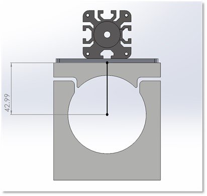
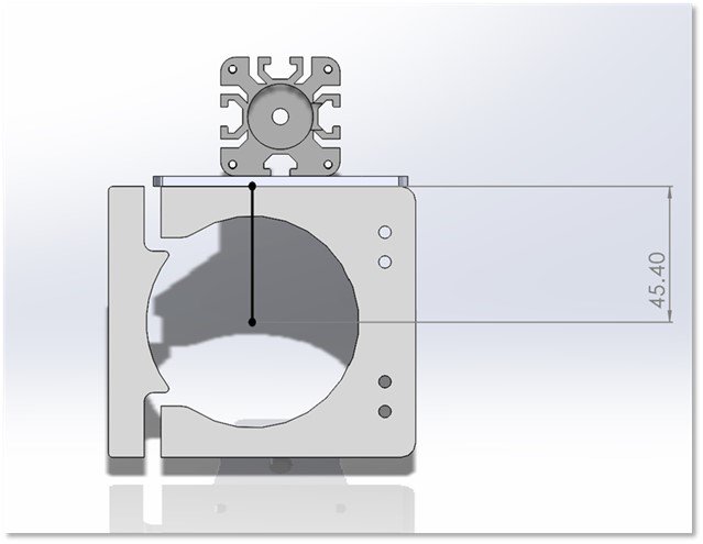
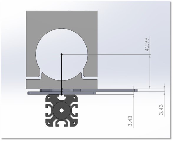
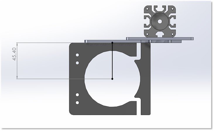
- We start by examining our assembly from the top view. We draw a line from the center of the router mount model, all the way to its front edge. The center of the router mount model will align with the center of the router/spindle, and thus gives an accurate center position:
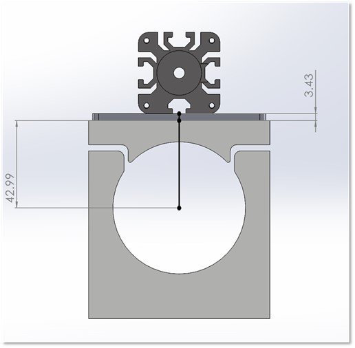
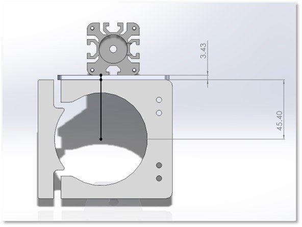
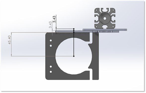
- Next we want to draw a line the length of the standard mount’s thickness. The standard mount and Vortex Riser mount both have a thickness of 0.135 inches. Thus we add a line that is 0.135 inches / 3.429 mm long:
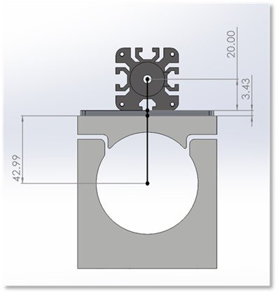
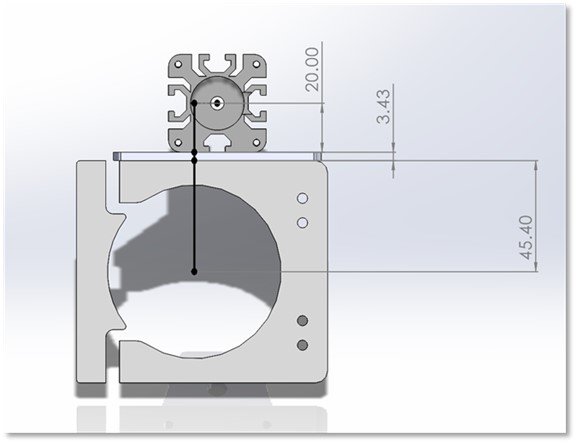
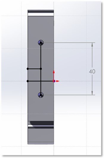
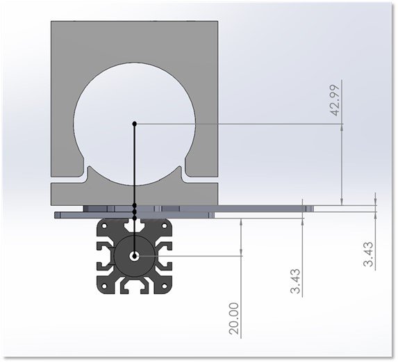
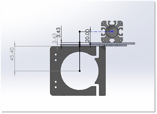
- Lastly, we add half of the LaserBeam diode’s width. The diode’s width is 40mm, hence we add a 20 mm line to reach the laser beam’s center:
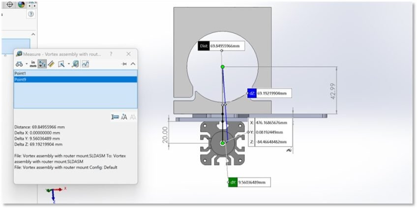
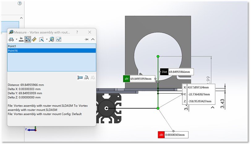
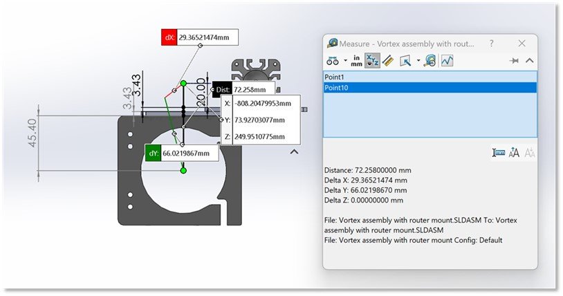
- We now measure the combined distance of the lines using the CAD software’s measurement tool. We can also simply add up all the distance values. Either method works fine:
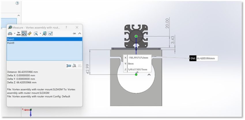
- Thus, our offset value is 66.42055966 mm in the y-direction. We could also have come to the same conclusion by analyzing the mount drawings available on the company resource page: https://sienci.com/product/router-mount-for-longmill-benchtop-cnc/
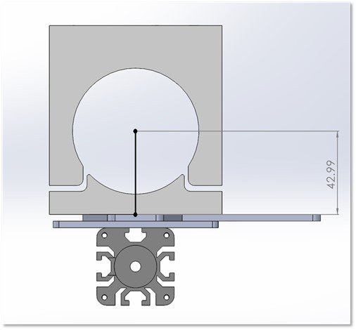
- In the engineering drawing for the 65mm router mount, the distance from the mount’s center to its front edge is given. It matches our CAD dimensions exactly:
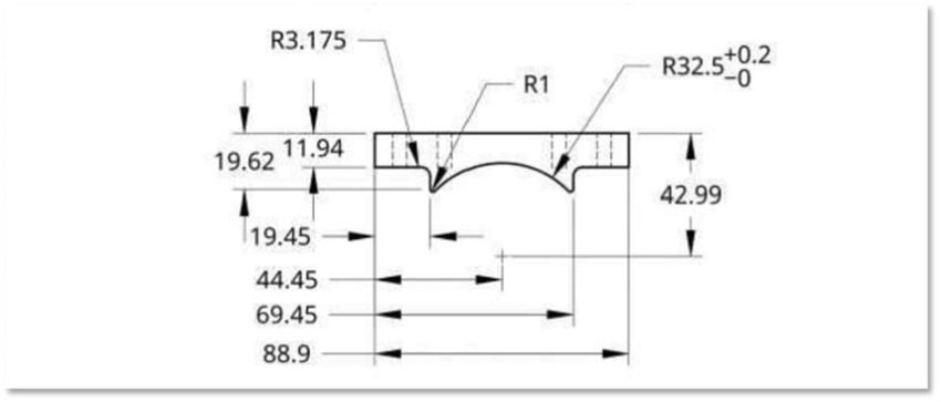
- With this information, one simply has to add the standard mount’s thickness, and half the width of the LaserBeam diode to get their offset value. Hence we would have 42.99+3.4163+20 =66.419. While not as accurate as the CAD model, due to the rounding of dimensions for the purpose of manufacturing, this method still works just as well. The difference in accuracy is negligible.
To summarize, the required offset value for the standard mount when used in conjunction with the MK1V4B-MKV2 is given by: (The distance between the mount’s center and front edge) + (the thickness of the standard mount plate) + (1/2 width of the LaserBeam diode)
This same formula was used to determine the offset value for the 71mm and 80mm mounts as well
- B) When used in combination with model MK1V1-MK1V4 router mounts, there is an offset in the y and x direction. We apply similar principles to find the needed values.
For this example, the 65 mm mount was used
*Note: for the MK1V1-MK1V4 models, the offsets are the exact same for the 52mm, 65mm, and 71mm router mounts. Due to how they were designed and manufactured, the offsets remain proportional as the only difference between said three models is the diameter of the router insert hole :
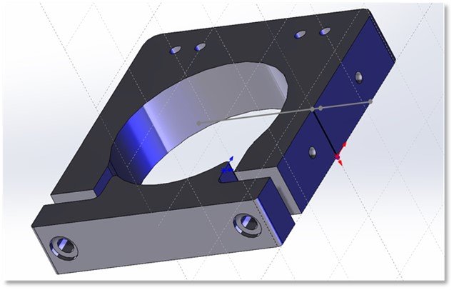
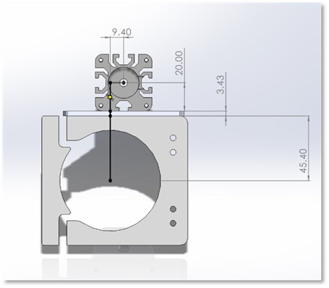
- Firstly, to determine the x-offset, we use the exact same method as we did for the y-offset in part a, but in the x-direction. This is due to the mounting holes being located on the router mount’s side face. We start by drawing line from the mount’s center to its side edge:
- We then add the width/thickness of the standard mount plate:
- We then add half the width of the LaserBeam diode:
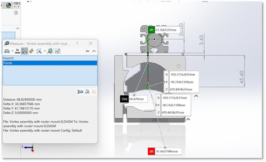
- Using our measuring tool, we find that this total distance comes out to 68.8163 mm. Thus this is our x-offset value:
- To find our y-offset, we extend a line down from our intersection with the side edge
- From here, we draw a line to find the distance between the two side mounting holes:
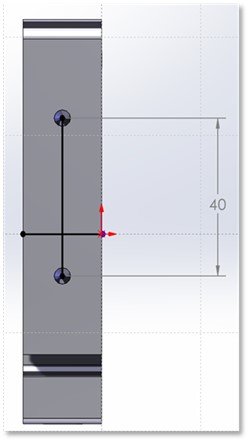
- From here we mark the centerpoint of the line that represents the distance between the mounting holes. We do this because the LaserBeam’s centerpoint would be located here when mounted:
- Now we measure the distance between the mounting hole line and the router/spindle’s centerpoint. This measurement comes out to 9.4mm, and thus 9.4 mm is our y-offset value:
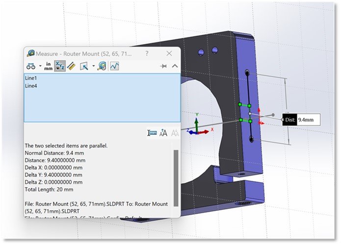
- We also could have simply just taken the x-measurement with our initial setup by drawing a line to the LaserBeam’s centerpoint. We see that we get the exact same result:
- To summarize, the x-offset is given by: (The distance between the mount’s center and front edge) + (the thickness of the standard mount plate) + (1/2 width of the laser diode), while the y-offset is given by the distance from the router/spindle’s center, to the center of the distance between the two side mounting holes
LaserBeam Vortex Riser Mount
- A) The offsets change depending on the orientation used, but the process is more or less the same. Let’s examine how the offsets were determined for orientation A
- Similarly to the standard mount in conjunction with models MK1V4B-MK1V2, this orientation only requires an offset coordinate in the y-direction. We start, once again by drawing a line from the center of the mount to its front edge:
- The LaserBeam Vortex Riser Mount is attached to the standard laser mount, and thus consists of two plates when fully assembled, each with a thickness of 0.135 inches, which equates to 3.429 mm:
LaserBeam Vortex Rise Mount Assembly
Thus to account for both plates, we will add two lines that are 3.429 mm long:
- We then add half of the diode width:
- Lastly we use our measuring tool and evaluate the total distance.We find our value is: 69.84955966 mm, meaning this is our y-offset value.
- Now examining orientation B, we now need to account for offsets in both the x and y directions. The y-offset values will stay the exact same as those associated with orientation A. This is because this orientation only changes the x-position of the laser, but has no effect on its y-position:
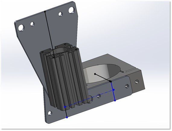
- Once again, we start from the center of the router mount and draw a line to the edge of its front face:

- The midpoint between the two vortex bracket mounting holes aligns with the midpoint of the router/spindle:
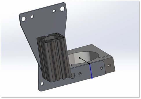
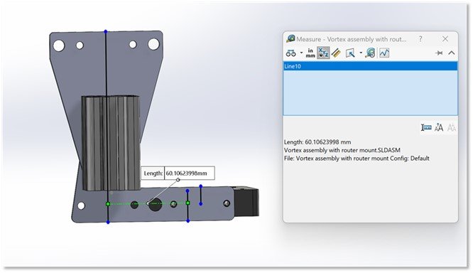
Thus, to find our x-offset, which is our distance between the centerpoint of the laser and the router/spindle, we need to find the length of the dotted line located in the photo below:
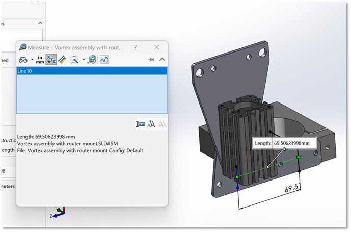
- Evaluating the line, we find that the distance comes out to 69.50623998 mm. Thus this value is our x-offset.
- While the same exact method can be applied to all other mount sizes, there is no need as this offset will stay consistent between all of them due to the fact that the center point of the bracket stays consistently aligned to the router/ spindle center throughout all versions. Thus to simplify, for the y-offset: (The distance between the mount’s center and front edge) + (the thickness of one of the Vortex mount plates) + (1/2 width of the LaserBeam diode)
X-Offset: 69.50623998
- We also could have simply just measured the distance from the top view. Doing so gives the exact same result:
C) Lastly, we examine the process for determining the offsets associated with orientation C .
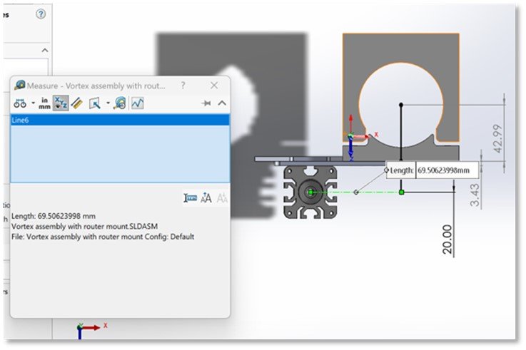
- Again, starting with the x-offset, the process is exactly the same as with the standard mount, but with a change in the width value we use for the plate. We first start with drawing a line from the midpoint of the router mount to the side edge:
- We then add the combined thickness of both vortex plates:
- Lastly we add the half width of our diode:
- Evaluating the total distance gives us an offset value of 77.258 mm for our x-offset.
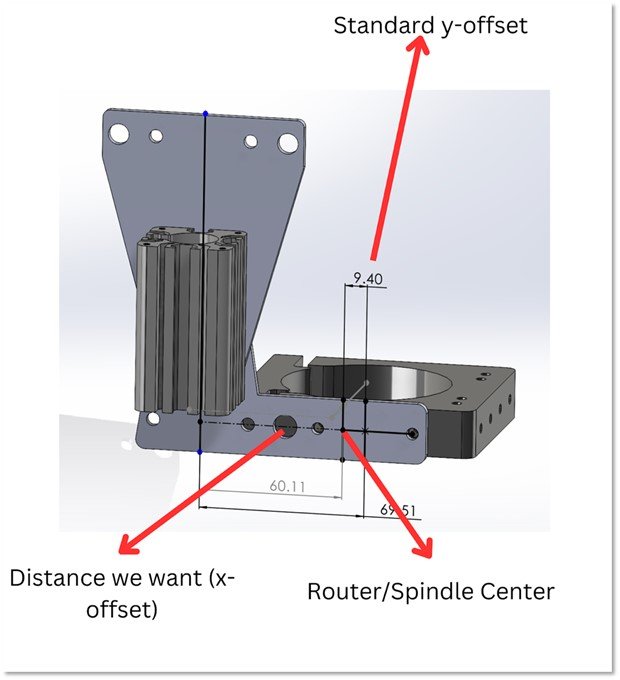
- Now to determine the y-offset, we simply subtract 9.4 mm from 69.50623998mm. This works because the vortex bracket aligns with the mounting holes, and hence the midpoint between the mounting holes on the bracket is the exact same as the midpoint between the two mounting holes on the router mount.
- Thus all we have to do is subtract 9.4 mm from 69.50623998 mm to get our y-offset. Hence our equation would be 69.50623998mm – 9.4mm = 60.10623998 . The photo below shows that this number turns out to be the distance between our router/spindle center and LaserBeam center.